Continue to Site

Eng-Tips is the largest engineering community on the Internet

Intelligent Work Forums for Engineering Professionals

  • Congratulations KootK on being selected by the Eng-Tips community for having the most helpful posts in the forums last week. Way to Go!

ASME B16.9 reducer thickness

TomoB

Mechanical
Dec 15, 2021
14
Hello,

I am performing a pipe stress analysis for a system and have encountered some confusion regarding the wall thickness of reducers.

After reviewing the ASME B16.9 standard, I found that no specific wall thickness is defined for reducers. I also searched through the forum and learned that, unlike EN standards, there are no standardized wall thickness values for these components.

From my understanding, design of a reducer is determined by the specified wall thickness of the connected pipe, i.e., the wall thickness at the ends of the reducer. However, the wall thickness and design of the reducer body itself are left to the manufacturer's choice, provided they comply with the ASME B31.1 code.

My question is: How can I determine the appropriate values to use for the reducer in my calculations?

Thank you for your time!
 
Replies continue below

Recommended for you

Measure it?

Or use the wt at the larger end of the reducer.
 
I believe you would just analyze the connecting pipe at wall thickness of the connecting pipe at the connecting pipe wall thickness and at the location of the connections. There is no analysis of the reducer sloping section or stress concentration factor applied to the reducer as far as I can remember.

In Caesar I think it was modeled as a pipe segment with average diameter and wall thickness of the connecting piping but it has been a while since I used Caesar.
 
Equivalent thickness can be calculated by weighing a sample fitting and applying a suitable geometric formula.
 
See ASME B16.9 2.2 .......fittings may have to be thicker than the pipe wall........
 
You do not need know the reducer wall thickness. The piping model uses the thickness of the connected pipe. The model also applied an SIF to the connected points. The reducer SIF only uses the slope of the reducer tapper and does not use the wall thickness.
 
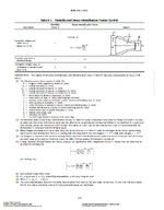
Looking further and as KevinZ indicated there is a stress concentration factor applied to the reducer (based on the connecting piping diameter and wall thickness). However, the SIF is based on the angle and also D2, t2- see attached.
 

Attachments

  • Reducer SIF.pdf
    472.8 KB · Views: 10
Last edited:
Find the schedule number (40/80/XS...) required as per the design pressure/MAOP. Find the thickness of pipes in reducer in ASME B 16.10.
 
Could not locate the SIF for reducers in B31.3 -2002 (referenced in the document above).

However, the recently introduced B31J-2024 provides experimental methods for determining SIFs.
 
Thank you for your responses.

Measuring or weighing the component is not an option, sditionally, my question is more general in nature.
For EN standards, the dimensions are clearly defined. In contrast, ASME B16.9 specifies, broadly speaking, that the reducer must be as strong as the connected pipeline.

I believe the pipe will likely be the first component to fail in this context, so I am not overly concerned about the Stress Intensification Factor (SIF). However, my concern lies in how the thickness of the reducer affects its stiffness. While this may not significantly impact the results, it will have some effect.

See ASME B16.9 2.2 .......fittings may have to be thicker than the pipe wall........
Sure, and how will that thickness be determined?
 
Hello,

I am performing a pipe stress analysis for a system and have encountered some confusion regarding the wall thickness of reducers.

After reviewing the ASME B16.9 standard, I found that no specific wall thickness is defined for reducers. I also searched through the forum and learned that, unlike EN standards, there are no standardized wall thickness values for these components.

From my understanding, design of a reducer is determined by the specified wall thickness of the connected pipe, i.e., the wall thickness at the ends of the reducer. However, the wall thickness and design of the reducer body itself are left to the manufacturer's choice, provided they comply with the ASME B31.1 code.

My question is: How can I determine the appropriate values to use for the reducer in my calculations?

Thank you for your time!
OP,
Don't expect the fitting manufacturer to be a Code Designer. You will need to specify the wall thickness of the reducer while ordering. The wall thickness (which is essentially rating) of the reducer is based on a seamless straight pipe of equivalent material.
For the calculation, the pipe size, wall thickness and pipe material that is equivalent to the fitting shall be used.
 
Are you doing FEA or something? Otherwise stress programs have this included.

You seem to be trying too hard here.
 
I don't see an SIF for a reducer in B31.3 2014 but there is one in B31.1 2016 - note that flexibility factor is 1

B31.1 Reducer SIF.png

(13) The equation applies only if the following conditions are met:
(a) Cone angle does not exceed 60 deg, and the reducer is concentric.
(b) The larger of D1/t1 and D2/t2 does not exceed 100.
(c) The wall thickness is not less than t1 throughout the body of the reducer, except in and immediately adjacent to the cylindrical
 
Last edited:

Part and Inventory Search

Sponsor