Continue to Site

Eng-Tips is the largest engineering community on the Internet

Intelligent Work Forums for Engineering Professionals

  • Congratulations KootK on being selected by the Eng-Tips community for having the most helpful posts in the forums last week. Way to Go!

ASME B31.3 flexibility analysis criteria 9

Status
Not open for further replies.

NovaStark

Mechanical
Feb 11, 2013
247
Good day all,

I'm trying to get some clarity for the criteria of Formal Analysis for Flexibility under ASME B31.3

ASME B31.3 said:
319.4.1 Formal Analysis Not Required. No formal analysis of adequate flexibility is required for a piping system which
(a) duplicates, or replaces without significant change a system operating with a successful service record
(b) can readily be judged adequate by comparison with previously analyzed systems
(c) is of uniform size, has no more than two points of fixation, no intermediate restraints, and falls within the limitations of empirical eq. (16)9

For (a) what exactly is meant by "Without significant change", if I change the material from carbon steel to stainless steel does that count as significant ? Or if I just add in a flanged joint, etc.


Can anyone with any experience assist me here?
 
Replies continue below

Recommended for you

This is where Engineering Judgement comes into play.

If you have never done flexibility analysis before you cannot understand the changes that can be made and still have an acceptable system.

Changing from carbon steel to SS is a significant change. SS expands significantly more than SS for the same temperature increase. Some type of flexibility evaluation (either computer based or simplified) should be done.

Addition of a flanged joint is, IMHO, a non-significant change to the flexibility of a piping system.

Increasing the diameter of an existing piping system is a significant change.

Review flexibility analysis criteria here:


MJCronin
Sr. Process Engineer
 
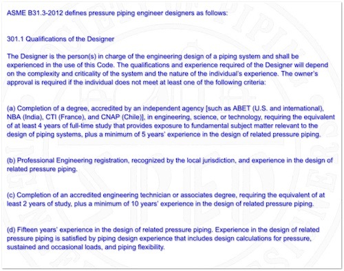
I agree that a material change is significant but then it is solely up to the designer to determine what is significant then.
 
Not a designer. The engineer that will be responsible for the design.
 
I think in this case the 'engineer' is the 'designer'.

asme_b31.3_designer_designer_mmwqyh.jpg
 
Minor differences can have a major impact. To understand when this can be the case, I think it comes to experience as MJCronin mentions.

The list of what is and isn't a possible influencing change is too long. Review of certain can however help on this, as with some standards. You may want to review the PIP practice on B31.3 flex analysis as an example, or get your hands on a copy of Peng & Peng's "Pipe stress engineering".
 
XL83NL said:
Minor differences can have a major impact. To understand when this can be the case, I think it comes to experience as MJCronin mentions.


That's what I was thinking as well so the experience thing seems to play a major role.

For example, I may go on the side of caution and say that an analysis is required for addition of a flange because I may not have the initial stress analysis on the piping to confirm that the piping isn't near an overstressed condition. But my supervisor may just say that the change is insignificant and flange could be installed which may cause problems later down.

(That isn't to say that I won't at least try to make a simple beam model of the piping system to see how stressed it is for my own peace of mind)
 
It's not only stress on flanges. I've seen piping systems where the stresses where moderate (i.e. < 50% of the allowable for the respective load case), but the flange was the issue: it would leak based on an VIII-1 app 2 analysis. Not only that, the nozzle of the adjoining vessel was severely overstressed.

Just an example ... (by the way this was for a 6" run at 1000F, 321 40S piping).
 
"without significant change" may mean a few % change in stresses, but unless you are just replacing like for like then you would need a lot of design experience to know how much difference there would be between modified systems.

Change in material is more than "without significant change".

It's not just thermal stresses that need to be looked at. Adding a flange or valve to a long run may not change the flexibility much but could make big difference to gravity and EQ loads/stresses.

 
@XL83NL

That's an interesting example.


@KevinNZ

That is why I was wondering about the various perspectives of how others would deem something as a "significant" change.
 
Anything that changes the structural stiffness of the piping system will cause stresses to differ. This is not as difficult as it sounds.

GENERALLY
A piping system is composed of long thin members, consequently there is little resistance to bending. Bending moments usually cause little bending stress. The pipe easily bends over its long lengths. Bending stress, Sb = Mc/I. Moments are typically low and pipe's I are relatively large, so bending stresses remain small. However bending resistance may be higher near end flanges attached to nozzles at equipments, vessels and tanks, where there can be some resistance to bending provided by the equipment. But that is not a very good idea, since it may overstress the equipment, so after the designer finishes his work and reduces those stresses, once again the pipe will have little relative bending resistance anywhere. (Reduce the pipe spans near equipment attachment points and the pipe diameter, if possible.) From this we see that we can keep bending stresses relatively equal between two different systems, if we do not change lengths too much. Bending stresses are proportional to the length of the member squared, but that's not soooo bad because bending flexibility goes up with the cube of L, reducing bending stresses even more. To be safe for changes in bending stress, increase pipe lengths. Direction changes, elbows, usually reduce bending stresses. Hence changes in direction are good for stress, but remember that they can adversely affect hydraulics.

Since bending stresses are relatively small, look at how axial forces are developed under thermal loading.

Thermal Axial Stress, St = E * [&alpha;]*[&Delta;]T
So, obviously, changes to
E, Young's modulus
[&alpha;], expansion coefficient and
of course temperature change,[&Delta;]T
initially are seen to have high consequences.
To keep stresses low, reduce any or all of those variable's values.

Since End Forces are developed as,
F = E * A * [&alpha;]*[&Delta;]T
Changes to pipe cross sectional area, A, will be significant to axial forces.
However if restraints are not present, no thermal force will be developed.
Therefore do not change the number or relative locations of axial restraints.
If you do, reduce, or preferably eliminate, the number of axial restraints in order to keep axial stresses low. No restraints = no stress. That is ideal, however expansion will maximize. The longer the pipe, the more relative expansion you will have.

Contrary to the thoughts of the inexperienced, changes in length do not effect axial stress at all, or end forces in the axial direction. However be very cautious making changes in cross-sectional area, A. How will A usually vary in piping systems? For the same internal operating pressure, changes in diameter can cause large changes in wall thickness, so in general, doubling the operating pressure, or pipe diameter will double cross-sectional area and that doubles all end forces accordingly.

Adding flanges do not necessarily cause any stress at all. What may be associated with flange stress increase is the resistance to bending that is added to the system by attaching those flanges to what can be rather (relatively) strong vessel walls, which can provide significant resistance when bending what is otherwise usually pretty long and flexible pipe.
 
319.4.1 Formal Analysis Not Required. No formal analysis of adequate flexibility is required for a piping system which:

(a) duplicates, or replaces without significant change a system operating with a successful service record.

THAT is easy to understand:

“NO SIGNIFICANT changes” - what does this mean?
1. The pipe geometry is VERY similar to a piping system that has been shown by analysis to be within the limits on stresses AND STRESS RANGES, (primary stresses and secondary stress ranges….YOU MUST UNDERSTAND COMPLETELY WHAT THIS MEANS);
2. The piping is operated at the same temperatures and the ambient temperature on shut-down is the same AND the system will see the same number of pressure – temperature changes in its expected lifetime;
3. The system is of the same pipe size and schedule, same material, same insulation, same contents, offsets and expansion/contraction loops are VERY close to being in the same locations;
4. The system has the same supports and restraints AT THE SAME LOCATIONS AND SPACING.

(b) can readily be judged adequate by comparison with previously analyzed systems.

Now you are getting into an area of nebulosity! This essentially calls for comparing the geometry of the new system to that of an existing system at the same location that has been formally analyzed.

To QUALIFY to make this judgment you should have:

1. A complete understanding of the ASME B31 Codes for Pressure Piping – that is to say you must understand the Code limits on primary stresses and secondary stresses and you must understand the theory on which these limits are based;
2. A significant amount of experience in “formal” piping stress analysis by hand calculation and/or computer modeling;
3. An adequate understanding of the load path(s) from the piping through the pipe supports and the structures to which they are attached ALL THE WAY TO THE GROUND;
4. A comprehensive knowledge of the various external loading that can be expected to act upon the “piping system” (dead loads and live loads);


Now comes the requirement that will “kick you out” to Para 319.4.2:

(c) is of uniform size, has no more than two points of fixation, no intermediate restraints, and falls within the limitations of empirical eq. (16)

Uniform size is easy to understand but really now, how many piping SYSTEMS have you seen that have no more than two “points of fixation”? As for “no intermediate restraints” - piping systems are supported and guided in accordance with B31.3 paragraph 321. (et al). What are “intermediate restraints”? “Intermediate restraints” are any device or fixture that supports, restrains or limits the movement of the piping – you are allowed a total of TWO!!! Have a good look at empirical eq. (16)! Run some numbers through that equation and come to an understanding of how LIMITING that equation is. NOW THEN, very carefully read footnote (9). Now, read it again – all of it. Equation 19 has been in the B31.3 Code for a long time without the committee having a complete agreement as to its value. Footnote 9 supplies some WARNINGS of the limitations of Equation 19 and those limitations should be understood and should be agreed upon by the owner of the facility that will include the piping system of interest.

Your question seems to imply that there is some doubt in your mind regarding application of paragraph 319.4.1. There SHOULD be some doubt in your mind. Re-reading Footnote 9 should bring an understanding of the doubt that exists in the minds of other very experienced piping engineers. There is an old cliché that tells us “When in doubt, build it STOUT”. Do yourself a favor and perform a logic guided well documented (and peer checked) piping stress analysis on the system and sleep well at night.
 
Excellent John. Although your answer may not give any 'hard' criteria, nor a definite answer to what the OP may have hoped, I think this is as close as you're gonna get into answering the OP's question. Of course you can write an article about it (or even a book, as has been done a few times - good books too, BUY THEM!), the summary of that article would comprise your reply.
 
Better than Christmas.
Good to hear from you again John.
You gonna hang around for awhile?
 
Thanks for the kind words fellow "pipers". My Beautiful Bride has "explained to me" that I am now retired!!!??? So, I guess that means no more hopping around the world - most of my travel will now be attending B31 Code Committee meetings and spending as much time in PA and Texas as MBB allows :). Gee, has it REALLY been THAT long? I guess MJCronin will have to rattle my cage more often!!
 
@JohnBreen

Thank you so much for your insights. XL83NL would be correct in saying that is not the definitive answer I expected but for all intents and purposes, that is the best answer for my question.
 
Welcome back John, you are the one of the best!
 
Status
Not open for further replies.

Part and Inventory Search

Sponsor