Eng-Tips is the largest engineering community on the Internet

Intelligent Work Forums for Engineering Professionals

ASME B31.8 and ASCE 7-16 Wind Load 1

Status
Not open for further replies.

structure_engineer

Structural
May 5, 2022
46
0
6
US
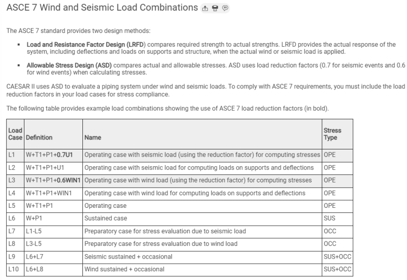
Since ASCE 7-10, the wind load is strength level for 1.0 Wind. For pipe stress calculations, do you use allowable stress design or strength level wind loads?

In COMPRESS Pressure Vessel Design Calculations, which is a Mechanical discipline related function, there is this section:

2022-12-29_09-34-59_tfsi3v.png


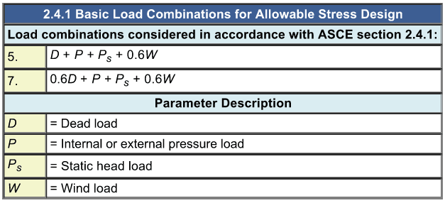
I have attached the load combinations of a vendor on a slug catcher stress calculation. It seems like they mix the strength level load factor with the nominal weight of pipe which is allowable stress design. I have no exposure to ASME B31.8. Thus, I am asking for any Piping Engineer who can help me to sort this out. I have downloaded ASME B31.8 and could not find any load combinations in the document. As far as I know, allowable stress design load combination could not be mixed with ultimate strength design load combinations. I have a set of load combinations for Load and Resistance Factor Design for structural steel members and a set of load combinations for allowable load values for pile design. There is very distinct difference between these sets of load combinations. In the attached file, should Load Combination 46 be like:

46 (OPE) W+T3+P2+0.6WIND1?

All load cases with wind load, there should be a 0.6 load factor? Your input is much appreciated. Have a Happy New Year!
 
Replies continue below

Recommended for you

.
If you are designing the slug catcher as a pipe under 31.8, the allowable stresses for pipe are given in B31.8, for "unrestrained pipe". A slug catcher is unrestrained, as it is not buried.

B31.8 does not have any load reduction factors.
Pipe Wall Design factor is 0.5, Or 0.4 if it is located in that area design classification.
Piping wind load is the wind pressure on a flat surface x shape factor of pipe.
Maximum wind is normally not coincident with other occasional loads, or hydrotest load.
Maximum wind is coincident with all operating conditions.

The design engineer is responsible for including any and all loads and combinations of load cases he deems relevant to successful performance.


Einstein gave the same test to students every year. When asked why he would do something like that, "Because the answers had changed."
 
My task is to design the pile foundation to support the slug catcher. Thus, I need support reactions in allowable stress level. I should go back to the vendor to request for the support reactions in allowable stress level?

Here is what I found on Hexagon's website:
2022-12-29_12-20-15_xjybvk.png


As you can see in load combination L3, Hexagon did specify to use the 0.6 factor when calculating allowable stresses due to wind event. I understand the slug catcher vendor had to do what is right to apply the maximum wind for all operating conditions to check the Code stress level based on ASME B31.8. However, mixing the allowable stress design load factors with the ultimate design load factors is something I am not used to do. I usually have one set of load combinations for pile reactions; and one set of load combinations for Load and Resistance Factor Design (LRFD) for steel members. I guess I could take the lateral shear force at the supports and multiply them by 0.6 and moved on. The little increase in vertical compression or tension due to the strength level wind will be ignored as I am on the conservative side.
 
I didn't understand that you were designing the foundation. You don't need to know anything about B31.8 or the vessel design codes to do that.

I don't think the foundation design needs any more than the following.

Design foundation for the usual ACI cases if concrete piles.
hydrotest with 1.4 factor
Size the foundation for uniform pile load with Operating + thermal sustained (all 1.4)
Check max pile load Operating with thermal pipe stress load, (1.4), if any, as a sustained load + wind at 1.7.
Check max pile load Operating with thermal pipe stress load (1.4), if any, as a sustained load + seismic at 1.7.
Check uplift and overturning at min load empty (0.9) and wind, or seismic at 1.7.

Or the AISC cases there if they are steel piles.

The pipe stress program probably calculated actual wind loads and then checked combined stress against the pipe's allowable stress. I dont think it should affect your work. It should list actual unfactored reactions which you will put on your foundations, factored or not, depending on the foundation design method you use..

Einstein gave the same test to students every year. When asked why he would do something like that, "Because the answers had changed."
 
The intend to post here is to get any input on what is the wind load per ASME B31.8. Is it ultimate strength design or allowable stress design? I have the document now and did not find anything regarding wind load load combinations. Also, I am not familiar with Caesar and wanted to see if the software has the reduction factor built in already. Turns out, it did not. It specifically says a separate load combination is required to have the 0.6 factor, based on their example of Load Case L3.

The 0.6 factor is from ASCE 7 load combinations, to reduce the ultimate strength level wind load to allowable stress design wind load. The consensus in the design team is that we can take the shear output of the stress report and apply a reduction factor of 0.6 to get the lateral load for the piles. There will be a little increase in the compression or tension in the pile vertical loads because the applied wind is in ultimate strength level. Thank you 1503-44 for your input and attention. Y'all have a very Happy New Year.
 
B31.8 is allowable stress based. No loads are factored, with the exception of road crossing traffic loads.

Einstein gave the same test to students every year. When asked why he would do something like that, "Because the answers had changed."
 
1534-44,
If that is the case, all load combinations associated with ASCE 7-10 or ASCE 7-16 wind loads should have a 0.6 factor. Do you agree? I could not believe the vendor could have missed that. This is a big miss. Mixing strength level loads with allowable stress loads is not a good engineering practice.

On the CAESAR II documentation L4 is defined as W+T1+P1+WIND1 and is meant for "Operating case with wind load for computing loads on supports and deflections." In my experience, deflection is always measured in allowable level, never in strength or ultimate level as that would be confusing.
 
There is no provision in B31.3, B31.4, or B31.8 for ultimate strength pipeline design.
Loads do not have factors. Actual stresses are calculated from unfactored loads and checked against Alowable stress is calculated by SMYS * DF. DF varies between 0.4 and 0.72 in most cases. Operating Stresses are limited to well below the yield level, minimum of 28% below yield, maximum 60% below yield, except in very limited circumstances that require special permission in the USA. Any stresses and deflection of pipelines from wind, thermal, soil, or generally any other loads are therefore never factored and are as real as the load applied.
Ultimate strength design only applies to structural items that may support a part or portion of piping, pipe racks, pipe supports, structural steel clamps, bridges, cable supports, concrete slab supports for large valves etc. When I do structural work, I don't care what the pipe B codes say. When I do pipelines, I don't care what AISC or ACI say. There is no connection whatsoever.
When you are doing pipe design, please remove your structural engineering hat. Caesar's loads are not factored. They check against allowable pipe stress that is based on some combinations of factors, each of which is less than 1, x SMYS. No plastic design stress is allowed during operation. It shouldn't even be close. Hydrostatic TESTING loads may sometimes hover around or slightly surpass yield stress, but entirely at the owner's option and risk, and ONLY during hydrostatic testing.

Einstein gave the same test to students every year. When asked why he would do something like that, "Because the answers had changed."
 
Maybe these are helpful.

From
LRFD refers to Load and Resistance Factor Design which is also a Limit States Design methodology. This method uses a load factor to ‘factor up or down’ service level loads and also reduce member strength based on reliability and statistical data. When using LRFD you must design the strength based on the LRFD load combinations and factors however deflection should be based on service level loads, so you must keep track of your loads!

In the 2005 AISC both the ASD and LRFD methods for determining nominal strengths are presented side by side. The nominal strength will be the same for both methods and only the allowable strength will differ due to the fact that the safety factor applied for ASD and the reduction factor applied for LRFD will be different.

So why the switch, whats behind it? LRFD is a more reliable and statistical based method for predicting loads and material strengths. Whereas the allowable stress saftey factors where based on engineering judgement and past experiences. It is debated which will give you a more efficient design however it seems in most situations LRFD will produce a smaller sized beam based on strength but not always. Also serviceability and deflection control many designs, in which case both methods will yield the same result as the design is not base on strength at that point.

Einstein gave the same test to students every year. When asked why he would do something like that, "Because the answers had changed."]
 
2023-01-04_12-02-29_yffznw.png


1503-44,
When CAESAR II uses ASCE 7-10 or ASCE 7-16 to calculate the wind load, without the 0.6 load factor, the wind load is already a factored load. I want to emphasize this point so whoever uses ASCE 7-10 or ASCE 7-16 to calculate the wind loads, they need to realize the wind load is a strength design forces.
 
It is quite confusing. Perhaps you wouldn't mind showing an example of all these factors. I thought only a shape factor was used. Flat wind pressure x 0.6 for a cylinder. That's what I use when doing pipe stress calcs.

Einstein gave the same test to students every year. When asked why he would do something like that, "Because the answers had changed."
 
Additionally, a dynamic increase factor might be warranted for longer spans subject to dynamic loading, vibration from wind or wave and current induced loads.

Einstein gave the same test to students every year. When asked why he would do something like that, "Because the answers had changed."
 
0.6 could be the shape factor for the circular pipe under wind load in case the wind load is produced for the diameter of the pipe only.
You need to investigate how the wind load was driven to be able to prove this is true.
 
Yes. That's the only way that it makes sense to me.

Einstein gave the same test to students every year. When asked why he would do something like that, "Because the answers had changed."
 
Just to be clear, 0.6 is not a shape factor. It is a factor to bring the ultimate level load down to allowable level load. As shown by ASCE 7-10 Section 2.4. See attachment. To give you an example, the minimum yield stress for steel is at 36,000 psi. The minimum tensile stress typically ranges from 58,000 psi to 80,000 psi. If you take the ratio of 36,000/58,000 that is a 0.62 factor, rounded to 0.6. If you inverse that ratio, 1/0.6 = 1.67. To put it simply, wind for ASCE 7-10 or ASCE 7-16 is at ultimate level, 1.67 if you will. To compute allowable stress level forces and to combine with the nominal weight of pipe, at allowable level, we have to reduce the ASCE 7-10 or ASCE 7-16 wind down from ultimate level load to allowable level load by using a 0.6 factor. See CAESAR II documentation, also attached.
 
 https://files.engineering.com/getfile.aspx?folder=e7c8e0fd-4948-4593-99d9-b6dc90b4373c&file=CAESAR_II_Manual_(partial).pdf
OK. That explanation also makes sense... for design of steel structures. Typical Piping design does not use ultimate yield strength at all; the check is against an allowable stress of X * "basic" Yield Stress. In most cases, we couldn't care less what UST is. Basic yield stress for hi tensile pipe is 60 to 70 Ksi. Ultimate is typically over 100. Been so long since I tried to find that, I don't even recall exactly what it was.

Einstein gave the same test to students every year. When asked why he would do something like that, "Because the answers had changed."
 
Structure_engineer,

You have provided the evidence of the factor of 0.6. This factor is used for checking the pipeline under stress limit state.

The others (ultimate limit state factors)are used for designing structure and foundation using ultimate state design, and controlling deflection.

I trust you do not have any confusion on the issue now.
 
I do not have any confusion now. The tricky part is how do I convey the message to the vendor, who is a third-party vendor, supplying the slug catcher to my paying client, that they have a big miss and mixing the ultimate wind load with the allowable piping load? My role is to design the foundation to support the slug catcher. Just to reiterate, the vendor supplied a 17,000-page stress report, and expect the structural engineer to comb through the report and come up with design of the foundation system to support the slug catcher. We have made more than one request to get them to supply the loads in the form of basic load cases only, the operating weight, the content weight, the wind load in the transverse direction and etc.; and we got shot down each time. All we got is a three-page summary, at the end of the 17,000-page report, the maximum loads of the 128 possible load combinations. To design the foundation system, we have to look at a governing load combination and gather the reaction for that particular load combination, to see how the system reacts to that particular load combination. It is when I was gathering the load combinations reactions, I had discovered the error. Thank you for your attention. This is a great board with good feedback from good engineers. [bow]
 
I worked at a number of USA largest engineering companies designing refinery column foundations, reactor buildings, flare stack fdtns, then at numerous gas operating companies and we never got wind or seismic loads from the vessel fabricators. We did get empty, operating and test loads, but that was it. We figured out what the wind and seismic and pipe loads were ourselves.

If it was the owner paying me, I would have calculated the loads myself and then I'd have to tell them the vessel/piping design was suspect and they should get it verified by an independent vessel engineer.

Einstein gave the same test to students every year. When asked why he would do something like that, "Because the answers had changed."
 
Status
Not open for further replies.
Back
Top