Hi there,
I have another question with regard to the ASME Section 8 Dev2 PArt 5. For the calculation of protection against collapse, we have three methods: Elastic stress; Limit load, and Elastic-plastic stress. Since I have good experience with nonlinear FEA I would like to perform Elastic-plastic analysis. What I am having a problem with is defining the limit for Elastic-plastic analysis. In the code it states that
"A global plastic collapse load is established by performing an elastic-plastic analysis of the component
subject to the specified loading conditions. The plastic collapse load is taken as the load which causes overall
structural instability. The concept of Load and Resistance Factor Design (LRFD) is used as an alternate to the rigorous
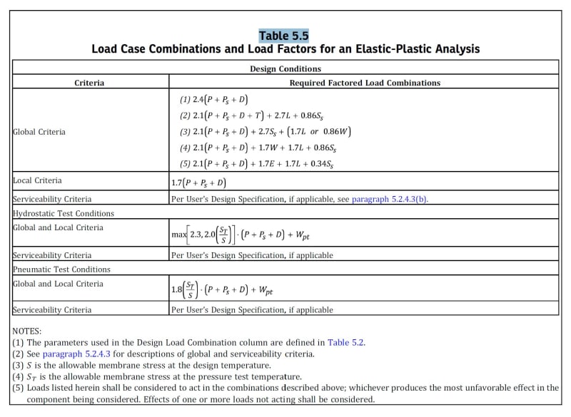
computation of a plastic collapse load to design a component. In this procedure, factored loads that include a design factor
to account for uncertainty, and the resistance of the component to these factored loads are determined using an elasticplastic
analysis (see Table 5.5).

On the figure, we can see that the LRFD has a factor of 2.4, which seems extensive.
Could someone please provide a bit of guidance on the limit for this type of plastic analysis
Thanks!
I have another question with regard to the ASME Section 8 Dev2 PArt 5. For the calculation of protection against collapse, we have three methods: Elastic stress; Limit load, and Elastic-plastic stress. Since I have good experience with nonlinear FEA I would like to perform Elastic-plastic analysis. What I am having a problem with is defining the limit for Elastic-plastic analysis. In the code it states that
"A global plastic collapse load is established by performing an elastic-plastic analysis of the component
subject to the specified loading conditions. The plastic collapse load is taken as the load which causes overall
structural instability. The concept of Load and Resistance Factor Design (LRFD) is used as an alternate to the rigorous
computation of a plastic collapse load to design a component. In this procedure, factored loads that include a design factor
to account for uncertainty, and the resistance of the component to these factored loads are determined using an elasticplastic
analysis (see Table 5.5).

On the figure, we can see that the LRFD has a factor of 2.4, which seems extensive.
Could someone please provide a bit of guidance on the limit for this type of plastic analysis
Thanks!
