MSL68
Nuclear
- Jun 23, 2023
- 3
ASME BPVC (Section III Appendix XIII-3100, or in older Code versions, this is described in the Definitions section) says "A stressed region may be considered local if the distance over which the membrane stress intensity exceeds 1.1S does not extend in the meridional direction more than 1.0*sqrt(Rt), where R is the minimum midsurface radius of curvature and t is the minimum thickness of the region considered.
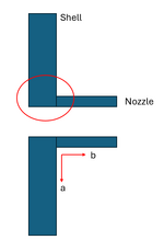
The only example the Code gives is based on an axisymmetric shell (Figure XIII-1300-1), and this requirement makes sense for this type of geometry. However, what is supposed to be considered R and t in the case of a nozzle in a shell? Is the "region considered" the entire shell/nozzle junction (circled in red in the figure), where the R and t values come from MIN(r.shell, r.nozzle), and similar for the thickness? If that is the case, should that distance be considered for the entire 'region considered', as in sqrt(Rt) is the length from 'a' to 'b'?
Or, would the shell and nozzle be considered separately, where a sqrt(Rt) is calculated individually with their respective geometries, and that length for the shell is arrow 'a', and 'b' for the nozzle?
My thinking is the first interpretation is more reasonable, because when you think about a infinitely large plate with a small hole, you would expect the attenuation length of the local membrane stress to be quite small and the size/thickness of the shell has little bearing on how it attenuates.