Hi,
I need to calculate the needed elongation or torque in order to tightening N°32 3"1/4 bolts in material ASME SA 193 Gr.B16 for the flanged joint of the channel cover of an high pressure heat exchanger (channel cover thickness 291 mm and channel thickness 200 mm, diameter 1934 mm).
I was reading ASME PCC-1 par. 10.2 "Bolt Elongation (bolt stretch) determination" and I didn't understand what are the terms "Sb: Target Bolt Stress" and "Leff: effective stretching length".
From appendix H I obtained the following:
Ar=4831 mm2
Ats=4961 mm2
Leff=41.275 mm (I don't know if this is correct, I consider half of the bolt nominal diameter, 82.55 mm)
So, from the formula in par. 10.2: DELTA_L=(Sb*Leff/E_young)*(Ar/Ats), where E=200000 MPa and assuming the target bolt stress equal to 70% of yield strength (655 MPa) --> 458.5 MPa I obtained DELTA_L=0.09 mm, that sounds me a bit strange. This because I understood that is a good practice consider the targer bolt between 40% and 70% of yield.
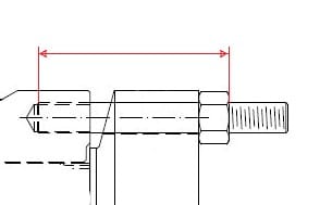
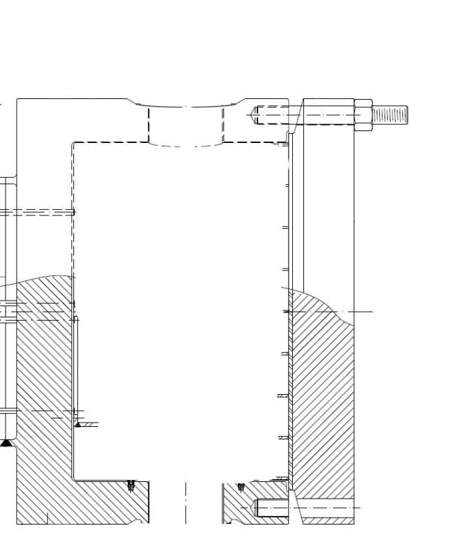
P.S.: between cover and channel there is a sealing diaphragm gasket in ASME SB 443 UNS N06625. Here attached the flanged assembly:
Thank you for helping.
I need to calculate the needed elongation or torque in order to tightening N°32 3"1/4 bolts in material ASME SA 193 Gr.B16 for the flanged joint of the channel cover of an high pressure heat exchanger (channel cover thickness 291 mm and channel thickness 200 mm, diameter 1934 mm).
I was reading ASME PCC-1 par. 10.2 "Bolt Elongation (bolt stretch) determination" and I didn't understand what are the terms "Sb: Target Bolt Stress" and "Leff: effective stretching length".
From appendix H I obtained the following:
Ar=4831 mm2
Ats=4961 mm2
Leff=41.275 mm (I don't know if this is correct, I consider half of the bolt nominal diameter, 82.55 mm)
So, from the formula in par. 10.2: DELTA_L=(Sb*Leff/E_young)*(Ar/Ats), where E=200000 MPa and assuming the target bolt stress equal to 70% of yield strength (655 MPa) --> 458.5 MPa I obtained DELTA_L=0.09 mm, that sounds me a bit strange. This because I understood that is a good practice consider the targer bolt between 40% and 70% of yield.
P.S.: between cover and channel there is a sealing diaphragm gasket in ASME SB 443 UNS N06625. Here attached the flanged assembly:
Thank you for helping.