Continue to Site

Eng-Tips is the largest engineering community on the Internet

Intelligent Work Forums for Engineering Professionals

  • Congratulations KootK on being selected by the Eng-Tips community for having the most helpful posts in the forums last week. Way to Go!

ASME Section VIII Appendix 2 - B value

Status
Not open for further replies.

Tomthumb67

Mechanical
Aug 6, 2020
13
Hi,

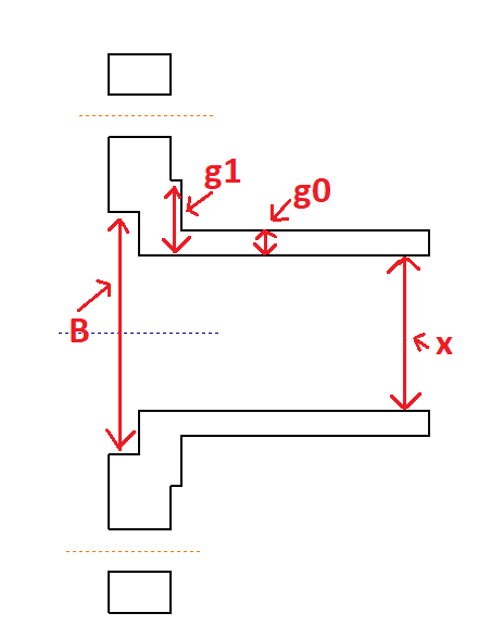
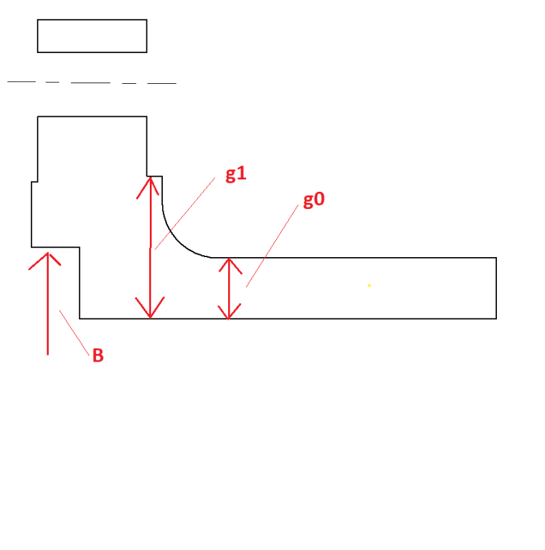
I want to make sure my assumptions are correct, is it wrong what I have considered for my inside diameter for the flange value "B", and for the hub thickness "g0" and " g1"?.
flange_ihxdch.png
 
Replies continue below

Recommended for you

Flange Diameter or flange size, is normally expressed in major standards such as ASME, DIN, EN etc., as the Nominal Bore Size (NB) which correspond to the smallest clear inside diameter.

Your sketch appears to show a flange. The size NB would normally be where the B is but in the horizontal plane.

What flange standard are you using or hoping to use? These would all give you the relevant dimensions, including the holes information for fasteners etc. You need to consider if the flange is made integral with a component, a loose slip on flange retained by a lap joint, welded o etc., plus the material grade and corresponding rating developed from the pressure and temperatures.

Per ISO-4126, only the term Safety Valve is used regardless of application or design.
 
Thanks for the response The Obturator.

What flange standard are you using or hoping to use? [This is custom flange I'm making, using ASME SECTION viii appendix 2 to design the flange.]

These would all give you the relevant dimensions, including the holes information for fasteners etc. [ If I use a standard like B16.5 then yes, all dimensions of the flange are provided. Unfortunately, I can't use the standard flange design]

You need to consider if the flange is made integral with a component, a loose slip on flange retained by a lap joint, welded o etc., plus the material grade and corresponding rating developed from the pressure and temperatures. [ Integral flange, cast carbon steel (WCB) , the pressure and temperature rating will be per

Let me know if I missed answering any questions.
ASME B16.34
flange2_xvx7gn.png
]
 
Just realised you're discussing ASME VIII Appendix 2. I should have read the title. Sorry, I don't have the expertise there and though you were discussing flanging in general. Hopefully someone will jump in to help.

Per ISO-4126, only the term Safety Valve is used regardless of application or design.
 
Tomthumb67, have you no copy of Apx 2? Your misconceptions should be obvious...

Regards,

Mike

The problem with sloppy work is that the supply FAR EXCEEDS the demand
 
SnTMan, I do have copy of the Apx 2.
The confusion for me is that Apx 2 shows in all integral flange figure that "g1" and "g0" is taken from the reference point of variable "B" but B is defined as the inside diameter of the flange and "g1 & g0" is defined as the thickness of the hub. I could not find text passage that showed when you have two inside diameters in the flange envelope, which should be considered for each variable. If you know the passage that will clear up this confusion it will be most appreciated.

As my figure has shown, my plan was to take the biggest inside diameter for variable B and have g1 and g0 taken from the small diameter. This best matched the description of each variable provided in the document.
 
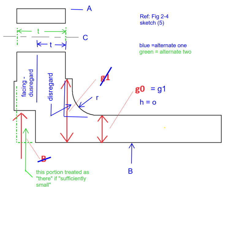
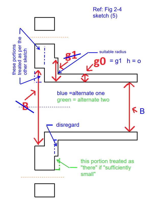
Tomthumb67, your flange designs do not neatly fit within Apx 2. You will not find language on how to treat two ID's, OD's, bolt circles, etc. There are ways to make calculations for your proposed designs by disregarding some portions of the flange, or alternately treating some missing portions as "being there", if sufficiently small. No definition offered.

The former case is used when a flange facing is present, see Fig 2-4, Note 4. Note facings may be male or female. The latter case may sometimes be used when a flange is designed as a packing box, using a braided packing rather than a gasket.

If I were to attempt to design the flanges you have shown I'd likely use one of two alternatives as shown on my markups of your sketches. I'd need an overwhelming incentive to do so. I much prefer to prepare designs for which I can easily perform calculations, rather than trying to fit calculations to a design for which they were not intended.

Regards,

Mike

flange_ihxdch_1_htjyki.png


flange2_xvx7gn_1_pneeuv.png


The problem with sloppy work is that the supply FAR EXCEEDS the demand
 
SnTman, Thank you so much. That makes it much sense.
 
Bit of a fudge :) Best of luck.

The problem with sloppy work is that the supply FAR EXCEEDS the demand
 
Status
Not open for further replies.

Part and Inventory Search

Sponsor