Eng-Tips is the largest engineering community on the Internet

Intelligent Work Forums for Engineering Professionals

ASME Section VIII Div 1 Nozzle Loads 8

Status
Not open for further replies.

RVAmeche

Mechanical
Jan 20, 2015
788
0
0
US
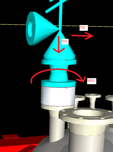
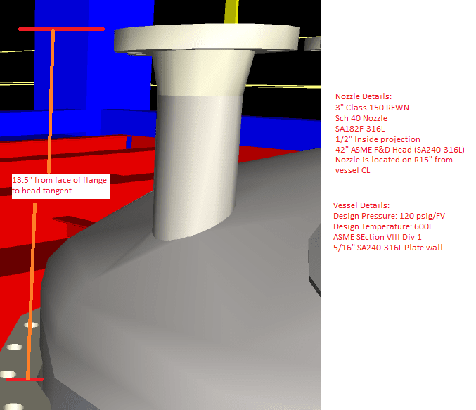
I'm working on a project involving a stainless steel ASME vessel rated for 120 psig designed to Section VIII Div 1. While doing the piping design, we identified high forces/moments on this 3" nozzle due to relief forces.

Nozzle_hchd3q.png


We sent the loads to the vessel vendor to try to confirm the nozzle is okay and/or propose reinforcement, but they basically said they can't run the numbers. They further stated the maximum bending moment this flange can withstand is approximately 19 ft-lbs, limited by the Class 150 flange and governed by MAWP reduction due to external load in their software. He said it'd need to be a Class 900 flange for the moments we were showing.

I'm not an ASME pressure vessel code guy but the 19 ft-lb response seems absurdly low to me. We're pursuing FEA analysis and preliminary results seem to be indicating a minor repad will be needed due to stresses at the head connection, but no concerns about the flange itself. Does this make sense and Div 1 is just absurdly conservative in this regard? It feels like we're missing something.
 
Replies continue below

Recommended for you

OP,
Not to say anybody is right or wrong, but what do the forces look like? PSVs can create quiet a large moment since the relieving force causing the moment is at a point above the flange. Consider that this isn't the vessel vendors first rodeo and dealing with relieving forces on vessel nozzles is fairly common. That said, the vendor saying "they can't run the numbers" indicated to me, either they don't understand the loads, or they haven't been given all the required information in the first place. There is also the issue how the loads are transferred through the PSV, which they truly may have no way of knowing or don't want to take ownership of, which is why they are putting it back on you. That said, I'm not sure they are communicating the exact issue properly back to you. I would consider looking into the PSV vendors information on determining reaction forces and how they are applied to the flanges. Most of the major PSV players have guidance for this if you haven't done this already. At the very least circle back around with the vessel vendor and have them "tell it to me like I'm a kindergartener".
 
I will give you some hints as we have dealt this a lot. 19 ft-lbs that can cause an issue is just a joke. Don't know who your vendor is.
However, you did not provide sufficient info for people to advise.
Where is the valve ? Figure out where the valve is and the direction of the reliving force which will be orifice open area x relieving pressure. Then calculate the bending moment at the face of flange, and check if there is any axial force through the center line of the nozzle due to the relieving force. If it is pure shear force at the face of flange, ignore it. That is why we need to see the reliving valve arrangement. Once you have bending moment and axial force, go to UG-44(b) to check flange rating. Very simple, not a big deal. UG-44(b) will tell you if you need to increase flange rating.

At the nozzle to shell junction: once you know the relieving force and direction, calculate the bending moment, shear force and axial force at the junction. The tricky part is, you need to do force and moment transformation to the directions based on WRC 107, also convert the head to a sphere in order to use WRC107. If it is 2:1 elliptical head, it will be 90% of the shell diameter as the radius of the sphere. For other type of head, you can use AutoCAD to measure the approximate radius, no need to be very accurate. For sure you can use FEA. Not difficult at all.


The relief valve is basically right on top of the nozzle, with a rupture disc holder between. We gave the vendor forces and moments (vertical & horizontal forces and bending moment). They said the flange failed from the bending moment alone and a Class 150 flange on this nozzle/vessel could only take 19 ft-lbs per Compress and it'd need to be Class 900 for the 600 ft-lbs we showed. I believe these numbers were run at the design temperature of 600F.

PSV_eqndfy.png
 
There is nothing unreasonable about the claim that a 19 ft-lb external moment applied to a Class 150 B16.5 flange could make it require a higher flange rating.


-Christine
 
Ask vendor to prove by UG-44(b), and ignore F(Y) because it is compressive to flange, not pulling out the flange. Ignore F(z) on the flange as it is shear. M(x) is only coming from F(z).
This is such a simple verification.
Check the nozzle neck, which has internal pressure with tensional stress and and F(Y) compressive stress, canceled some stress, nd bending stress from F(Z)x moment arm, very simple.
Check the reinforcement at the junction, also very simple.
I saw so many people using Compress or PV Elite, many times are just garbage in garbage out, not understanding the basis to see what is the problem.

This is such a simple task. Good luck.


External forces from the piping are not allowed, this may cause leaks in a closed safety device.
You can add 2 gussets 90° each, welded to the flange.
Be careful (design temperature? thermal insulation?...etc.)

Try to avoid incresing the flange rating.

Regards

 
There is no such thing as "external forces from piping is not allowed". I am living in a real world, have been handing if not thousands but hundreds of vessels with all kinds of materials and sizes.
All things must be proved by stress analysis as that is the essence of all codes for safety. The only and simple way in code to prove it may or may not leak is by UG-44(b.)
We do adding (2) bracings for size 2" and below only, not 3". This is also very common practice through industry to prevent nozzle deflection or damage during shipping. TOTAL, which is France oil company, in one of our project does not want any bracing as it can cause corrosion or cracks on the fillet weld. So we use LWN for small bores.
We use 300# flange as minimum for instrument nozzle (level gauge, TI, Pi, PSV) which has more bolting than 150# to prevent leaking, and can take much more loading.
RVAmeche you are stuck with 150#, a careful stress analysis is required. Any bracing won't pass jurisdiction. May be 300# is good enough, depending on the analysis per UG-44(b). Good luck and bless you.

 
OP,
How is the relief piping configured? Is this a open discharge? Typically, the atmospheric relief discharge piping is through a long radius elbow up to the atmosphere. Details are found in API 520-II.
The Reaction Force will cause the max bending stress at the interaction of the relief valve inlet pipe and the vessel head, NOT in the mounting flange.
The 150# inlet flanges for both nozzle and relief valve seems adequate for F182 F316L. Many clients, however, for example, Shell prescribes a 300# valve discharge flange rating for a 150# inlet to take up the bending stress from the discharge Reaction Force. Additional support is required to resist the weight and the Reaction Force. Refer to API 520-II.


GDD
Canada
 
@jt1234

1) “External forces from the piping are not allowed”, I refer to the discharge line

All discharge lines shall be run as direct as is practicable to the point of final release for disposal. For the longer lines, due consideration shall be given to the advantage of long‐radius elbows, avoidance of closeup fittings, and the minimizing of excessive line strain expansion joints and well‐known means of support to minimize line‐sway and vibration under operating conditions.

2) “The only and simple way in code to prove it may or may not leak is by UG-44(b.)”. Wrong
Leak test is the only way.

Regards
 
r6155, don't mislead people. We are talking about flange and nozzle, not the entire vessel for leak testing. P-T rating is the only way per code to check flange good or bad, with additional requirement from UG-44(b) if you are designing vessel based on Div. 1. Period.
 
You've got two issues going on:
1) Your nozzle is very close to the knuckle of the head. The stresses in the nozzle-to-head junction may require an FEA to determine if they are acceptable.
2) Do NOT use the UG-44(b) Fm values - instead, use the Code Case 2901-1 Fm values. That will greatly assist you. But, as GD2 notes, you may still need to up-rate your flange a little (to Class 300).
 
OP,
Not sure if this link will answer your questions but:
They said the flange failed from the bending moment alone and a Class 150 flange on this nozzle/vessel could only take 19 ft-lbs per Compress
This talks about how Compress analyzes flanges.

So, your firm is doing the pipe design and from what you said
I'm not an ASME pressure vessel code guy
Does your firm have someone who is? If not, who specified the vessel in the first place? or is this a vendor designed vessel, ie, give them general information they do the rest? The person who specified this vessel, should be able to answer your questions but if this was solely vendor design, you or someone at your firm is going to need to learn how to work through the BPVC if you want any grounds for pushback. As noted with any software, GIGO and the vessel designer may not have inputted things properly, just consider, you may do the same when you are trying to model it. If time is of the essence, then your firm may consider contracting a 3rd party to review the vessel design.
 
Thanks Heaviside

Generally when we specify a vessel it's just the basics like materials, MAWP, nozzle locations, etc. Even if we've already done the pipe stress and provide nozzle loads in the spec most of the times they'll say "minimal loads only are allowed" and we're basically back in this situation. Vessel vendors seem to always play the schedule card and say we could do it but it's going to delay you by 3 weeks or something.

We're actively getting FEA done, I was just floored by the 19 ft-lb response.
 
OP,
You or your firm's owner should really consider getting someone up on going through BPVC, it will give you a lot better visibility on the whats, wheres and whys concerning bids, schedule, fabrication and inspection and whether or not a vendor is acting in good faith. It can save you a lot of time and money in the long run and it provides an independent second set of eyeballs to make sure all the i's are dotted, and t's are crossed. Just my thoughts, good luck!

One additional, I thought someone would have brought this up by now but consider your design temp and what that does to the flange pressure rating. Without any external loading I think you're only looking at around 20 psi between that and your vessel MAWP, not a lot of room to play with.
 
@ jt1234
Leak testing can be performed on the nozzle without using the pressure vessel.
You mentioned "leak", but you are very confused again.
It's clear: you don't understand the calculations and you have no experience in manufacturing and inspections.
I don't mislead anyone, try not to be aggressive.

Regards
 
Why are we talking "External Nozzle Load", WRC 107, FEA etc for this nozzle? It's NOT a process nozzle. It's any other nozzle like instrument connection, inspection nozzle and manway nozzles.
Simply follow API 520-II installation guideline for the PSV and you should be good.
Yes, if it is atmospheric release, there will be high stress point at the vessel/nozzle intersection, which is taken care by the API 520-II guideline. If the release is to a closed vent, nothing to worry about as the Reaction Force will have minimal effect.

GDD
Canada
 
GD2,

I don't agree with that statement at all. It is a process nozzle, it's connected to piping that will get hot, and the reaction forces (atmospheric release) are not insignificant. This is stainless steel piping at 300-600F so it grows a decent amount - the 4 ft horizontal section of discharge piping on the valve outlet grows 1/8". It's nowhere near as trivial as a TT connection like you imply.
 
Status
Not open for further replies.
Back
Top