Eng-Tips is the largest engineering community on the Internet

Intelligent Work Forums for Engineering Professionals

ASME VIII-2 Part 5 - Use of bilinear material models for plastic verifications 1

Status
Not open for further replies.

Raul Villalba

Mechanical
Jun 20, 2022
10
0
0
ES
Dear All

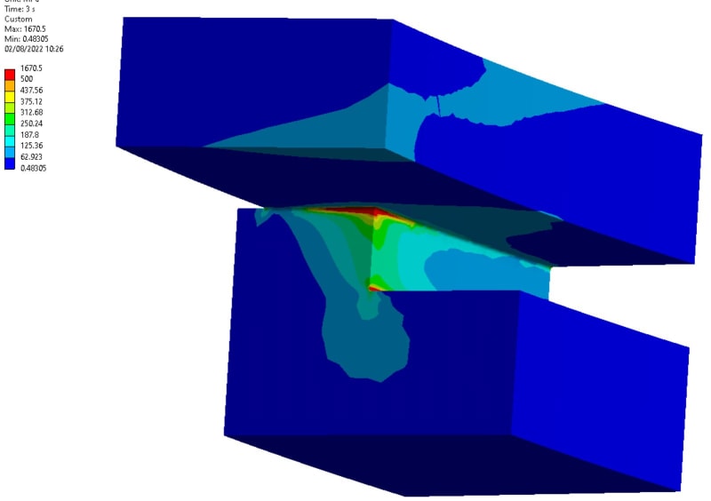
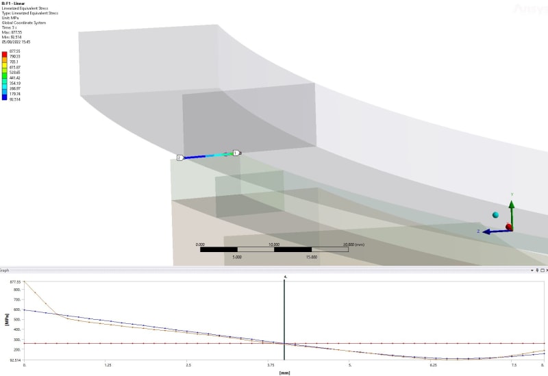
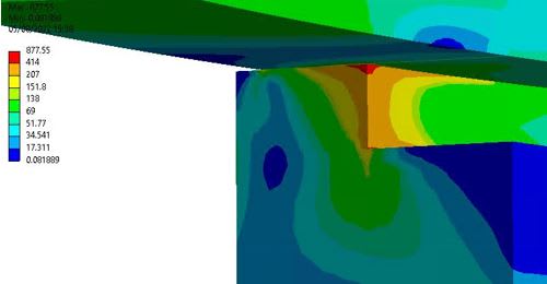
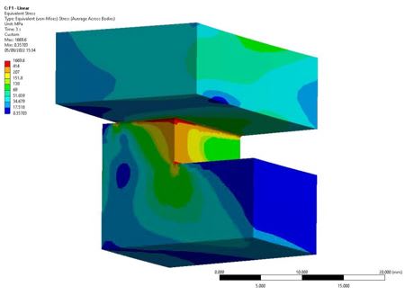
I am assessing a component following ASME VIII-2 Part 5. I have a region (rounded well meshed corner) with high stress concentrations leading to localized plastification. Material model of each verification:

- Plastic collapse: limit load 5.2.3 elastic perfectly plastic bilinear material as specified in 5.2.3.5 step 3.

- Local failure: elastic-plastic 5.3.3. Can I use a elastic perfectly plastic bilinear material instead of a multilinear material since it will lead to more conservative results? The material model in 5.3.3 is not very clear and it just indicates "Elastic-plastic stress analysis" in 5.3.3.1 step 1. In 5.2.4.4 step 3 it allows the use of both: elastic perfectly plastic or material with hardening.

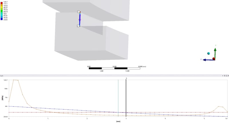
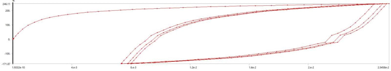
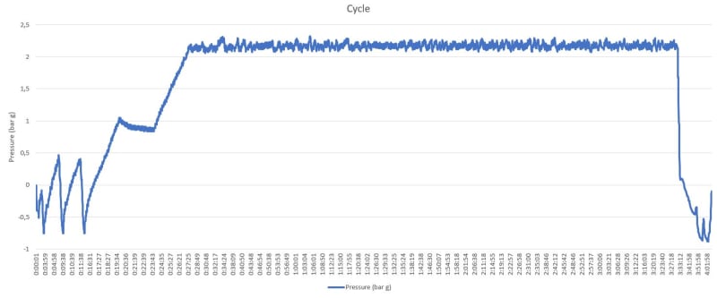
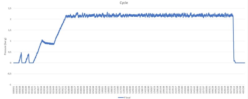
The vessel pressure follows the first load cycle, however the region under analysis is summited to the second load cycle since negative pressure causes a contact opening. Furthermore, unloading may produce a residual compression stress but I do not know yet the hysteresis stress-strain loop.
P_cycle_jdmjhl.jpg
P_local_cycle_j52wpm.jpg


- Fatigue: Elastic-plastic 5.5.4. There are two methods to obtain the effective strain range:
1. Cycle-by-cycle: Kinematic hardening must be included --> I will go for kinematic bilinear hardening material​
2. Twice Yield Method: No details --> I will go for an isotropic bilinear perfect plastic material​

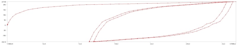
How can I demonstrate that twice yield method can be applied? As far as I know, the two branches of the stress-strain loop needs to be symmetrical.
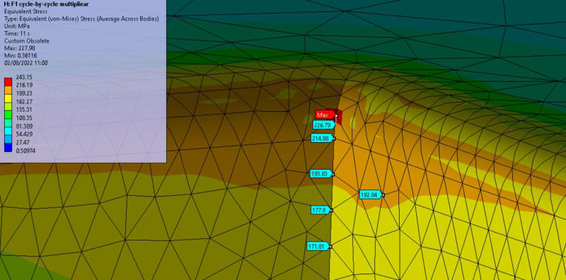
Can I use a bilinear material instead of a multilinear material (more conservative)? For cycle-by-cycle, is it possible to neglect the kinematic effects if I verify that compressive residual stresses do not exceed compressive plastic yield stress with Bauschinger correction factors?

- Ratcheting: Elastic-Plastic 5.5.7 with bilinear material as specified in 5.5.7.2 step 3.

Thank you in advance.
Warm Regards.
 
Replies continue below

Recommended for you

For 5.2.3, a Limit Load analysis is acceptable.

For 5.3.3, the requirement is to use a multilinear curve - it is not possible to say whether an EPP material model is conservative or not.

For elastic-plastic fatigue, if your material does not exceed yield in compression, then I would recommend not using elastic-plastic, but simply using elastic fatigue with appropriate correction factors.

For ratcheting, you may be able to pass the analysis with elastic ratcheting.
 
Thank you for your answer.

With respect to fatigue assessment, there is a notched zone under multiaxial non-proportional load with plastification. The local zone and its cross section do not comply with criteria 5.5.6.2 needed for values of correction factor Ke.k greater than 1, according to 5.5.3.2 step 4. This is the reason of why I have discarded elastic fatigue analysis. Do you agree or can I still using elastic fatigue trough 5.5.3.3?

When using cycle by cycle method for plastic fatigue, I do not understand how I should use strain-stress amplitudes curves from Annex 3-D.4 as indicated in 5.5.4.1-c and 5.5.4.2 step 4. In my case, effective strain ranges are calculated with equation 5.43 from stabilized cycle results of an elasto-plastic model with material properties from Annex 3-D.3.
 
Have you excluded the peak component in your assessment of the primary + secondary, M+B? Excluding thermal, is this stress range still greater than Sps? If not, use the elastic method and include plasticity correction factors if the Sn,k range is greater than Sps.
 
I have excluded peak component with a classification path in the direction of the principal component S1 (>>S2) since cross section path classification is not well defined. M+B is around 500 MPa > Sps = 345 MPa.

Elastic linear analysis
Stress ranges and linearization path. Sub-model with rounded corners of R0,25 to minimize singularities stresses:
Local_zone_nht2o2.jpg

Stress_linearization_mfazhh.jpg


Elasto-Plastic multilinear kinematic hardening
Plastic strain values of the main cycle:
Plastic_strain_tzrmgf.jpg

Hysteresis loop of Signed Von Mises Stress vs total strain of the main cycle on the worst node:
Histeresis_br266x.jpg


I would say that elastic method is not valid. I am currently performing elasto-plastic (5.5.4) and assessing the worst point with ΔSp.k=384 MPa, Δεpeq.k=0,011, Δεeff.k=0,013, Salt.k=1260 MPa and S-240 316L, which lead to Nº=250-500 cycles when our target is 6000 cycles.

Fatigue assessment node:
corner_qyvfyi.jpg
 
The linearization line should be perpendicular to the principal stress, but now seeing your results it appears likely to be outside the elastic range. Have you also performed the EP ratcheting assessment?

The twice yield method can be applied with the load range applied in a single step. If it is non-monotonic, you will need to apply each range separately, starting from the initial condition at points of inflection. However, if you are relying on plastic shake down then the cycle by cycle method is probably the way to go.

The EP methods may not be sufficient, the part may still need to be redesigned or a higher strength material used.
 
These stress contours confuse me. Can you please re-plot the stresses, but with the following contour intervals:

0.5*S
1.0*S
1.1*S
S[sub]PL[/sub]
S[sub]PS[/sub]
A Large number

And where exactly is your SCL? I see some high peak stresses, but nothing that would indicate that you have some description of cyclic plasticity that would require you to go to a EP Fatigue analysis. What is the driving force behind your peak stresses? Is it geometry only or it is thermally-driven?

I second the idea to proceed with an EP ratcheting assessment. I would be OK if you pass an EP ratcheting assessment and then proceeding with 5.5.3.2 Step 4 (Ke), and then stay with the elastic fatigue.

One final note, an elastic-plastic fatigue analysis has to use the stabilized cyclic stress-cyclic strain amplitude curves from Annex 3-D.4, and you would definitely NOT use the curve from 3-D.3.

 
Reply to BJI
You are right. With a correct linearization path Membrane+Bending range = ΔSn.k = 600
lin2_ykx1dr.jpg

Yes, I have performed an EP ratcheting which is compliant with criteria 5.5.7.2 – step 5 – c. Total deformation of the component does not increase with cycles.
totdef_hldke4.jpg


Reply to TGS4
Von Mises stress from elastic analysis under max pressure value of the load cycle.
rerere_x4zok5.jpg

deff_yyubvm.jpg

Same but with a submodel with rounded corners:
smm_ldepv2.jpg


Peak stresses appear due to geometry. EP ratcheting is passed. Proceeding with 5.5.3.2 Step 4 (Ke) for ke>1 needs to accomplish the criteria of 5.5.6.2 which is not meet since ΔSn.k (without thermal stress)= 600 MPa > Sps. Am I wrong?

How am I supposed to use the curve from Annex 3-D.4 in this assessment? Equivalent stress range and equivalent plastic range are obtained from equation 5.43 using simulation results. Then the effective alternating equivalent stress is used in Annex 3-F to find Nk.
Signed equivalent von mises vs sum of principal total strain of the most severe node from EP analysis with multilinear kinematic hardening material: (Stress & strain ranges from the last cycle are similar to those from stabilized hysteresis loop which will be reached according to EP ratcheting verification):
loop_pgiu8p.jpg


Should I cyclically apply the amplitude of my loading cycle with material properties from 3-D.4?
 
Status
Not open for further replies.
Back
Top