What if the actual surface controlled with a regular equal bilateral profile tolerance with respect to a fully constrained DRF fully lies on one side of the true contour? How would you report this in terms of two-sided evaluation?
The actual limits to that deviation. What is the maximum material and what is the minimum material - if they are both material minus then, for example on an equally disposed 0.06 tolerance one case might be:
-.01 for material+ compared to the defined material+ 0.03 (0.06/2) limit and
-.02 for material- compared to the defined material- -0.03 (0.06/2) limit
engineering might simply want to know
They might want to know a lot of things. They might want to know how orientation affects it. But every thing I want to know has to do with performance of the feature and will have a tolerance for it. If flatness is a a requirement then it will be a refinement; anything else is passing curiosity and not engineering.
By way of example - a rectangular prism has 12 edges. Each edge is represented by a nominal 90 degree angle. Does inspection ever just go off and add 12 lines for those face pairs to the report because engineering might want to know the angularity between all face pairs?
Still - it would be a separate requirement from the profile to trace where the request for information came from. If it's not on the drawing inspection needs to justify the cost of performing the flatness check and reporting the flatness result so it would be a separate sequence number.
---
I was making clear that if there are people reporting basic dimension variation then Y14.5 is losing the fight and those won't be people paying to get a copy of Y14.45. For them Y14.45 is a checkbox on the CMM software and they will figure out some way to get the values from the CMM onto a page.
I have previously contrasted Y14.5 with programming languages, with the difficulty for Y14.5 being that there aren't compilers or interpreters widely available for Y14.5. Instead it ends up just as bad as if anyone were to try to learn to programming by talking to other students about what a computer might do and believing their program they wrote by hand would work as they expect it to without error. It doesn't matter how much individuals are expected to "study" Y14.5. Once they get it wrong they will tend to remain wrong. This makes the scattershot overused condition where training materials. particularly in the standards, showing easy special cases a real problem.
How tough is "
Basic dimensions have no variation so no variation can be reported for basic dimensions. If you feel otherwise, tell your employer you have both made a terrible mistake in your hiring." Put that in the footer of every page.
---
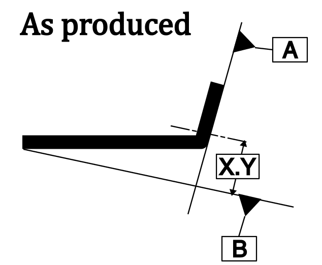
I think the failure in the Y14.5 standard is from using the document as a cheering section, avoiding showing applications where the acceptable result is far from the naive expectation - I failed several times to convince coworkers that for mounting holes the face they were drilled into was sometimes a poor choice for the primary datum reference. The worst was a formed flange - if the flange was bent to an outside face angle that was slightly less than 90 (as springback was likely to do) then the resulting position of the hole with respect to the nominally parallel face would be unwanted.
where the flange had a +/- 1 degree tolerance (though angularity would be as relaxed similarly) with this variation exaggerated in the diagram. The horizontal portion was about 30 inches wide - 0.017 * 30 inches > 0.5 inches vertical displacement vs. the dia 0.030 position tolerance.
The argument would be that the inspectors would use a height gauge from datum feature B to check the basic location and that it was important to have datum feature A as primary to make sure the hole was perpendicular to that face. In the 0.030 sheet that would be (0.017*0.030 = 0.0005 inch lack of perpendicularity for datum feature B as primary.
Does any standard show this potential pathological case, a very common problem, and indicate why it's bad? Of course not - it's a perfectly valid callout to have A primary and B secondary. It's used all over the standards for position tolerance. The standard writers are cheerleaders who will not show their favorite tool being misused in any way.
Lacking some access to the equivalent of a compiler or interpreter that works only off the evaluation rules and can generate geometry that is acceptable to the requirements to show it will accept unwanted parts, it's just a free-for-all.
In my case - manufacturing told management that engineering was stopping production. Management was uninterested in understanding engineering - they got MBAs so they didn't have to - but did understand missing delivery dates to a customer who had penalties for late deliveries. I could go to the standard but that showed, when a datum feature surface was penetrated by a hole, that datum was always primary.
---
It's not a "convention" when the ASME Y14 committee is alone in doing so. "I" doesn't come before "A" and mixing Roman Numerals with Alphabetic characters as heading identifiers isn't conventional.
Per IEEE guidelines:
Appendix headings are a special case.
The primary heading(s) in the Appendix or Appendixes (note
spelling of plural) are set according to the usual style, except that there is flexibility in the enumeration of the
heading. The author may use Roman numerals as heading numbers (Appendix I) or letters (Appendix A).
Also - the page numbering was jacked up. Didn't notice until I went to search for page 98 per the table of contents and there isn't a page 98. It looks like the table of contents was frozen but the automatic numbering wasn't when the Foreword, et al, was suppressed.
It is an example though - MS Word is an interpreter for .doc and .docx files. Even if the issuer thought the table of contents would match the sections, the interpreter operates according to the set of interpreter rules and generated an acceptable document even when it's not what would be desired.