Eng-Tips is the largest engineering community on the Internet

Intelligent Work Forums for Engineering Professionals

Assistance producing a FBD to assess forces on a restraint bolt

Status
Not open for further replies.

AMG100

Mechanical
Nov 29, 2023
8
0
0
GB
Hi,
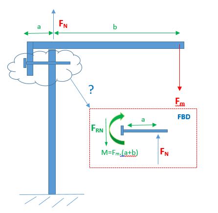
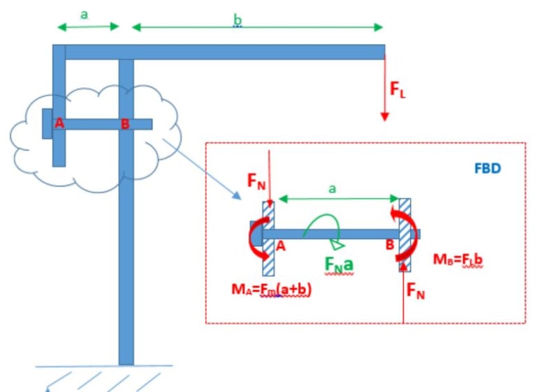
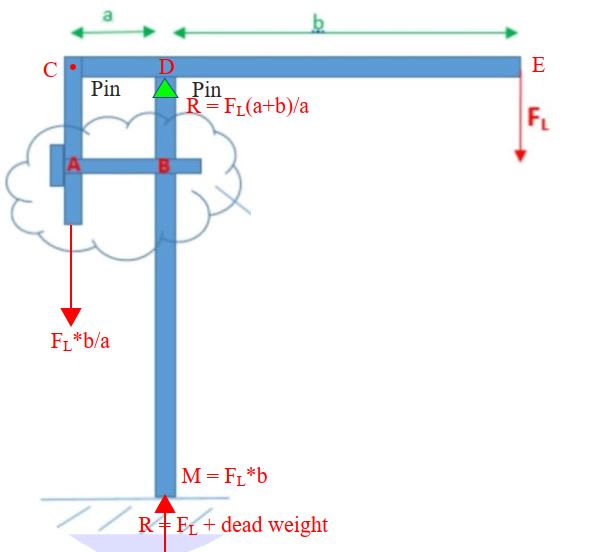
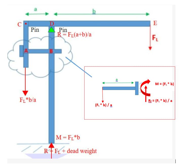
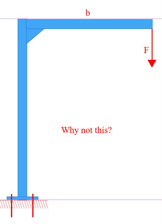
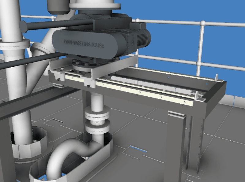
I was hoping somebody may be able to help me generate a FBD for the forces imparted onto bolt/pin located which is designed to prevent rotation of the simple structure shown in the image below
FBD_Query_vk0e02.jpg

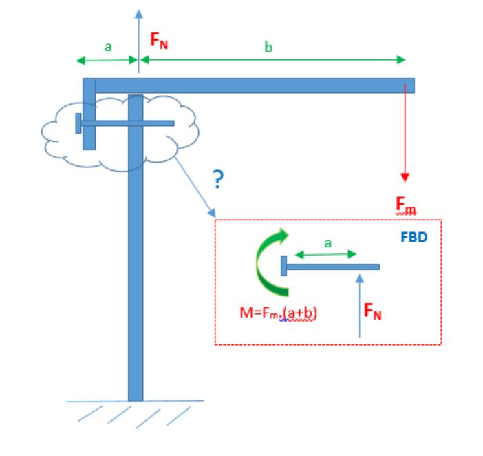
I am assuming that the bolt has moment arm applied at its head (M)due to the applied force (Fm) and the shank has a normal reaction force due to the contact made with the upstand but wanted to check whether these assumptions are correct and the loads appropriately calculated. The plan is to use the FBD to resolve the forces and then determine the bending stress and shear forces on the bolt/pin to make sure it is adequately sized.

If someone who is much more skilled at these things than myself could cast an eye over and advise as to whether I'm on the right track with this, that would be really appreciated.

Thanks in advance,

Anthony.
 
Replies continue below

Recommended for you

Hi, apologies I just noticed that at the head of the bolt I have missed a reaction force to compensate for the force acting on the shank so the FBD should have looked like:
FBD_Query_q50yjf.jpg
 
no ... the nut is equally a restraint ... the bolt is a doubly fixed beam.

And your FBD is still in error ... the standing leg, the attmt to "the rest of the world" is reacting a moment F*b ... so the LH end of the bolt has moment F*(a+b) and the RH end has moment F*b, and the force couple of F (in the bolt) reacts a moment of F*a.

"Hoffen wir mal, dass alles gut geht !"
General Paulus, Nov 1942, outside Stalingrad after the launch of Operation Uranus.
 
Hi,

Thanks for the response. If I understand your response correctly (?) your logic is as follows:

1. The RHS side of the bolt (Point 'B') is contact with the grounded upstand post which imparts a normal (vertical) reaction force of F onto the bolts contact surface, equal and opposite to the applied load i.e. F (Normal)= F (Applied) = F
2. The RHS of the bolt also experiences a clockwise moment due to the applied load which is resisted by a counter-clockwise moment of (F x b) at the bolt/upstand connection.

Note: I am assuming here that it is the bolt end which is exposed to the loads/moments incurred by the applied load and not the connection between the upstand post and horizontal section of the 'L' piece which is considered to be a rigid item - is the correct thinking?

3. The LHS side of the bolt (Point 'A') also experiences a clockwise moment due to the applied load which is resisted by a counter-clockwise moment of (F x (a+b)) at the bolt head.
4. To preserve equilibrium, the LHS side of the bolt must also counter the reaction force imparted by the upstand onto the RHS side of the bolt, producing an equal and opposite (downward vertical) force of F.

Hopefully so far so good, but the last bit of your statement re. the 'force couple' confused me slightly. Am I correct in thinking you mean the following:

The LHS side of the bolt is required to produce an equal and opposite force to the reaction force imposed by the upstand on the RHS of the bolt. The resultant effect of this balanced force pairing is to create a 'couple' of magnitude (F x a) which I assume applies at the centre point between the bolt ends ?

If my interpretation above is correct then the FBD for the forces / moments acting on the 'fixed' ends of the bolts looks something like :
FBD_Query_2_qi35on.jpg


I'm hoping I'm on the right lines with this but your feedback would be appreciated, thanks.
 
the applied moment at A is CW, the reaction torque couple and the reaction moment at B are CCW (and balance the moment at A)

Is there a gap above B ? (there was in the 1st post. No gap changes everything.)

"Hoffen wir mal, dass alles gut geht !"
General Paulus, Nov 1942, outside Stalingrad after the launch of Operation Uranus.
 
Sorry my mistake the 'upstand' is not connected to the horizontal section of the (continuous) 'L' piece which is free to pivot - the bolt provides the constraint to prevent this rotation. My statement above re. the connection being rigid is incorrect.

Does this arrangement effect the above statements?

Thanks for the help.
 
Many thanks for this response. It occurred to me last night when rb1957 queried the presence of the gap, that the removal of this and replacement with a pivot, should simplify should the problem and your response confirms what I was thinking which is great.

In terms of the loading on the bolt am i correct in thinking this can now be modelled as simple fixed cantilever beams as follows:
FBD_Query_3_qljfo0.jpg


One query, does the RHS of the bolt see any of the reaction force at the pivot / ground. I'm thinking not on the grounds of the bolt not being in contact with the pivot or the floor (I'm assuming these forces would only come into play if you wanted to check for buckling) and the fact it has to be in equilibrium with the load applied to the LHS (FL*b)/a - hopefully this is the correct logic?

Many thanks for you help with this!
 
ok, change the problem ...

but if you're going to include "dead weight" in the reaction, then you need to apply it as a load, and change everything ... the fixed moment reaction would be F*b + dead_weight*(b+a)/2-a =(b-a)/2, and the reactions at A and C change too ...

I don't like having the bolt react the offset couple at one end, it should be at both ends, but this really complicates the solution.

"Hoffen wir mal, dass alles gut geht !"
General Paulus, Nov 1942, outside Stalingrad after the launch of Operation Uranus.
 
AMG100 said:
One query, does the RHS of the bolt see any of the reaction force at the pivot / ground. I'm thinking not on the grounds of the bolt not being in contact with the pivot or the floor (I'm assuming these forces would only come into play if you wanted to check for buckling) and the fact it has to be in equilibrium with the load applied to the LHS (FL*b)/a - hopefully this is the correct logic?

I don't understand your query. The red text is a double negative which makes no sense at all. The blue text mentions buckling; buckling of what? The bolt or the column? The bolt will bend in double curvature but will not buckle. The column must be designed to prevent buckling.

Beam CDE is pinned at D. A downward force of F[sub]L[/sub]*b/a is required at C to prevent the beam from simply rotating about the pin at D and collapsing. The only thing that prevents collapse is Bolt AB; if it is assumed to be rigidly connected at each end, it has a moment of (F[sub]L[/sub]*b/a)a/2 = F[sub]L[/sub]*b/2 at A and B. The bolt bends in an 'S' shape.

Using a bolt in pure bending is not something I would do and I suggest you devise a different scheme for your project. I asked you in my last post, why not weld the beam to the column and forget about the bolt, but you did not respond. I ask again.

Capture_otjh1b.jpg
 
is this a project, so you can do what you like, or an assignment, so you have to answer a specific question, or just some random thought exercise ?

"Hoffen wir mal, dass alles gut geht !"
General Paulus, Nov 1942, outside Stalingrad after the launch of Operation Uranus.
 
The answer to your question is that is a project which involves the design of a carriage which is required to manoeuvre a heavy valve into a position which allows internal maintenance of the valve to be undertaken - arrgt shown below.

The objective here was to simplify the set up and simulate an absolute (and I appreciate completely unrealistic) worst case which I've done by considering only one half of the support frame with the weight of the valve sat on the carriage assumed to be taken by only one of the bolts/pins which is inserted to secure the carriage in place. The ultimate objective is to check the size of the bolt (which in reality is performing the function of a pin) offers adequate strength to resist any potential bending shear forces.

Setup_u5wzv9.png
 
thx for sharing ... this student forum is possibly not the best place, I was thinking this was a school assignment.

Can you show how this tool fits onto the structure ? Why do you need the bolt as shown, when there are many other approaches that would be much "better" from a structural point of view. If you are considering an extremely conservative analysis approach, then let us know ... otherwise we'll think this is the structure and critique. We don't know what's going inside your head !!

"Hoffen wir mal, dass alles gut geht !"
General Paulus, Nov 1942, outside Stalingrad after the launch of Operation Uranus.
 
I assume that to do maintenance on the valve, you would need to detach it from the pipe above and below, slide it out on the carriage and lift it up to give access to the bottom of the valve. Could the valve be suspended by a vertical power screw attached to a frame or tripod above the valve?
 
Status
Not open for further replies.
Back
Top