Continue to Site

Eng-Tips is the largest engineering community on the Internet

Intelligent Work Forums for Engineering Professionals

  • Congratulations KootK on being selected by the Eng-Tips community for having the most helpful posts in the forums last week. Way to Go!

Australia - Embedded retaining wall design

Status
Not open for further replies.

dangee

Geotechnical
Dec 8, 2018
3
Hello,

I am interested in understanding what codes engineers typically adopt in Australia to design embedded retaining walls. I'm primarily interested for the design of secant/diaphragm walls on commercial projects. For example, deep basement excavations (multi-propped/anchored/etc), rather than for embedded walls on government infrastructure projects (that I presume would use the bridge code).

A cursory examination would seem to imply that AS4678 should be the default standard. But after limited investigation, I could only find a single reference to "embedded pile" walls under Appendix E1 and the guidance here was to follow the recommendations of AS2159 for laterally loaded piles. Furthermore, Figure 1.1 would indicate that embedded retaining walls aren't really covered and that the code is primarily for gravity walls. Though, this is not stated in plain English.

Is there any general consensus on this? Do you just make AS4678 "work" for embedded walls? Do you adopt a recognised international standard (e.g. BS8002, either EC7 compliant or an older version) that specifically addresses these types of walls? Adopt the bridge code? Use AS2159? Or something entirely different.

Cheers.
 
Replies continue below

Recommended for you

As5100.3 appears a better one. CIRIA C580/760 is a very commonly used reference for embedded retaining wall design.
 
Normally I design the wall with WALLAP using "average" soil parameters and then apply a 1.5 factor to the moments/shears in accordance with Section 4.2.3 of AS1170.0.
 
Thank you Henryzau and Retrograde both for your responses. Very much appreciated.

I am familiar with the approach in CIRIA C760 and would hazard a guess that the EC7-DA1C1 described there would give you reasonably similar (but lower) design forces then if you were to adopt Retrograde's suggested AS1170 with a factor of 1.5.

I'm not so familiar with AS5100.3, but from what I have seen, I believe you also carry out your analysis based on working loads and then factor by 1.5. But I haven't looked at this in detail...

So it would seem that perhaps a good way to go is adopting something similar to the older CIRIA C580 approach, with a working load analysis adopting "moderately conservative" parameters with and factor of 1.5 on the bending/shears forces (as opposed to 1.35). An additional check with factored down soil resistances or "worst credible" parameters (with no additional factor on the output) is probably a good idea too. To check that you don't get very large changes in the magnitude or distribution of the design forces due to differences in soil-structure interaction.

To be honest, I was surprised that there wasn't very much guidance on this. I had imagined that there would be a few notable position papers on an alternative approach given AS4678's non-existent guidance. Perhaps they were there and I just didn't find them... I did find a good paper by Day, Wong and Poulos that effectively sums up the quagmire regarding the design of retaining structures. But unfortunately, they do not propose a solution.

As an interesting aside, I note that the Queensland Department of Transport and Main Roads adopts BS8002 (I believe the 1994 version) for embedded retaining wall design. I'm not sure why they don't use AS5100, or something else a little more modern. The old version of BS8002 seems a bit of a mixed bag.
 
dangee,

I also run FEM (Plaxis/Wallap) using unfactored soil parameters, then times the wall forces by 1.5 for structural check. My opinion on BS8002/AS4678 is that they are more or less for hand calculations, I would never use factored strength/modulus in any FEM program. I only use factored soil strength in hand calculation to check toe stability for multi-strutted embedded retaining walls. I suggest you read AS5100.3 Sup which explains why unfactored soil parameters should be used.
 
Would you guys mind telling me how you undertake the structural design of embedded walls. I am newish to all this and still trying to learn.

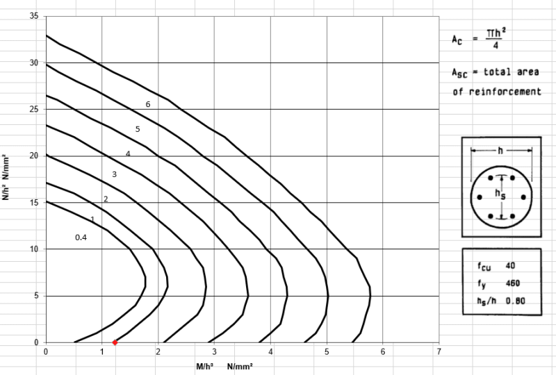
One method i have seen, which is based on the British Standard, is to use the concrete column charts,which determines the % of longitudinal steel required based on your shear and bending moment? See below.

Concrete_column_tyxgsm.png


Shear reinforcement is calculated based on the As required formula below. with V being the Ultimate shear force divided by the area of concrete. and Vc based on (BS8110: PART1, TABLE 3.8)

shear_ymjipp.png
 
UP830 said:
Would you guys mind telling me how you undertake the structural design of embedded walls.

I use reinforced concrete column design software to do the structural design.
 
HENRYZAU said:
I suggest you read AS5100.3 Sup which explains why unfactored soil parameters should be used.

I assume you mean Clause C7.3.3?

AS5100.3 Supp 1 - 2008 said:
This unfactored approach to the geotechnical modelling is taken because, in the case of soil-supporting structures, both the applied loads and the resistance of the wall system are a function of the soil parameters. To take a factored approach and modify the soil parameters by a capacity reduction factor to establish a geotechnical model to determine the resistance of the system changes the entire geotechnical model such that it no longer represents a realistic model of the actual structure. When such an approach is adopted, the geotechnical model is not realistic and the geotechnical engineer can be misled regarding the geotechnical behaviour of the structure (for example, maximum bending moments in the wall may change in position as well as quantum). Further, when the analysis is conducted using computer modelling, the design engineer is even further removed from the reality of the actual geotechnical conditions.

I've always found this curious. The factored soil parameters are essentially a sensitivity check and I've never come across geotechnical engineers who said they were completely confident that a design geotechnical model was a perfect representation of the ground conditions and response to loading. If different soil parameters change the position of the maximum bending moment substantially, this should be investigated otherwise reinforcement curtailment or reduction in steel wall thickness may be made at unconservative locations. Or is there a general assumption that the 1.5 load factor will paper over any such issue?

On the subject of the 1.5 load factor, doesn't that also represent an unrealistic model of the actual structure? What is the physical condition that would result in those stresses in the structure? Maybe gravity changing from 9.8m/s/s to 14.7m/s/s (not sure) but I'd say that's less likely than getting the soil parameters wrong. In short, it seems more rational to investigate the sources of uncertainty than to increase the stresses by an arbitrary factor.
 
Steve,

No, the factored soil parameters are NOT a sensitivity check. Using partial factors to factor down soil/rock strength is a ultimate limited state check while a sensitivity check on Cu, c' & tan(phi') is still a serviceability check.

Load factor 1.5 doesn't change the force and moment distribution rather it increases the magnitude of the force/moment. And it's for structural check to make sure it's robust/safe.

Adequate SI work should be carried out to have a reasonable understanding of ground profile, strength and modulus to reduce the uncertainty. CIRIA C760 is a good reference for embedded retaining wall design.
 
In my opinion the quoted passage from the Supplement to As 5100.3 is just wrong. The whole point of ULS design is to design for the worst combination of high loads and low strength that might occur in practice, so a ULS analysis will be a better model of the actual structure when it is close to failure.

There are three good reasons for using unfactored loads and soil properties, with a higher load factor:
1. It makes the analysis procedure much simpler, especially when soil-structure interaction is important.
2. There is a long history of application of this approach, whereas there is little published review of practical application of the ULS approach.
3. Soil stiffness is usually important in soil-structure interaction problems, but there is very little guidance on appropriate factors for ULS design.

For those reasons I use the AS5100 factor of 1.5 on the structural actions coming out of an unfactored analysis whenever I can, but that doesn't mean the analysis is a more accurate model of the actual structure at close to failure conditions, because it isn't.


Doug Jenkins
Interactive Design Services
 
Thanks for the replies, Henry & Doug.

I think Doug's point #2 is important - the AS5100.3 method is effectively the old working load method but with the ~1.5 reduction factor on permissible stress moved to the other side of the equation as a stress increase so that limit state structural codes can be used; ie using traditional geotechnical analysis (and knowledge) with current structural codes. (The last line in the commentary reads to me as a swipe at computer analysis by an old engineer who just wants to be left alone to work the way he/she always has rather than being a valid objection.)

I was brought up on limit state design and think it makes sense generally, but had always thought geotech work was even more suited to it given the greater non-linearity compared with structures. This could be important if the wall has large compression loads such as a wharf with container crane supported by the wall.

Despite what the commentary says, the code itself requires consideration of sensitivity and recommends conservative parameters (so perhaps not as realistic as suggested by the commentary), which is how it should be. So maybe the objection is to fixed reduction factors specified in a code rather than considering the circumstances for each project.
 
I may regret commenting after only skimming the paper but my initial thoughts are:

- Why are calculation cases 1-5 even being considered for the purpose of predicting/matching structure behaviour at service (non-ultimate) conditions? Case 0 with a sensitivity check is the appropriate way.

- Figure 8b has one case (out of only 22) cases where a 1.5 factor on design action effects has the calculated 'ultimate' bending moment less than the measured bending moment, and another three cases where the design ultimate bending moment is approx equal to the actual bending moment during construction (as I understand it). Although I don't see where the article specified how these predictions relate to structural design - I've just assumed 1.5 per AS 5100.3.

Is there a similar paper that considers walls that failed? That would be more relevant to the assessment of ULS methods. I suspect not, which was one of Doug's (IDS) points.
 
Status
Not open for further replies.

Part and Inventory Search

Sponsor