Eng-Tips is the largest engineering community on the Internet

Intelligent Work Forums for Engineering Professionals

Autocad P&ID Symbols 2

Status
Not open for further replies.

S. J.

Mechanical
Aug 9, 2018
6
0
0
MD
Hi,
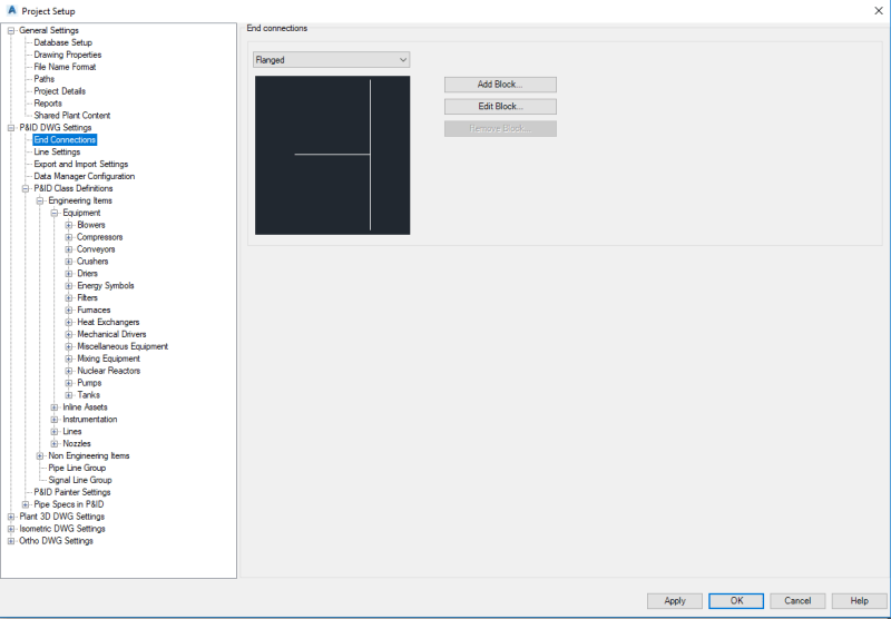
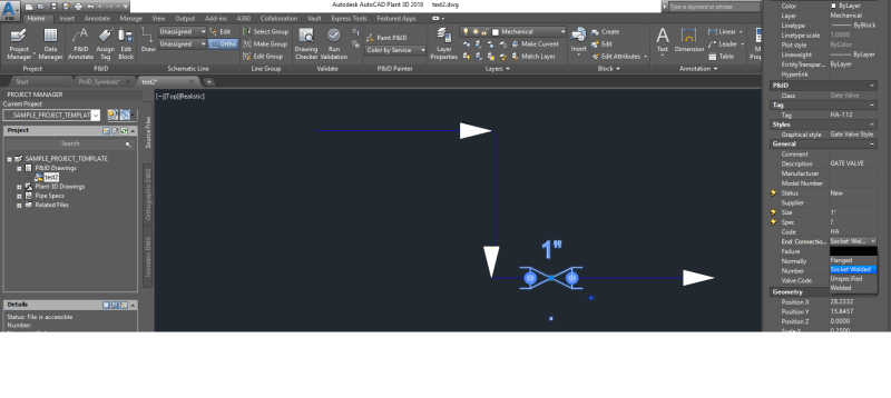
I am attempting to make my 1st very simple P&ID in Autocad 2018 & can’t get Valves, Fittings to show with Threaded connections. Could someone please provide some help as to where to find the info to do this, I can get Welded & Flanged connections but do I need to do something in Spec Editor? Specs are not an issue just yet as only making the practise drawing for now.
Thanks
 
Replies continue below

Recommended for you

IMO going through the effort of showing every end connection for all the valves is tedious and not worth the hassle. The end connections of the valves are spec driven and you would have to verify them every time you wanted to draw a valve on the P&ID.

Plus there is also a higher risk of human error by accidentally assigning the wrong end connection to the valve. Sometimes the Client will want them shown and in that case, you just have to be very aware of what the spec calls for if you are drafting or checking the P&IDs. Sometimes 2" valves are flanged, sometimes socket welded, sometimes threaded. Just depends. But regardless of what the end connection is, the valve is still needed so, to me, just show the valve and keep rolling.

The feature in AutoCAD just allows you to show them a little easier if you need to use it.

Thinking is hard work. That's why so few do it.
 
S.J.,

Let me try to ask a few more questions before answering further.

1) What software are you using?
2) Does your company standards require you to show the end connections?
3) Is this work for a client? If so, does the client standards require you to show end connections?
4) Also, you mentioned you were trying to show end connections for "fittings" as well. What fittings are you attempting to show on the P&ID?
5) Are you attempting to utilize "smart" P&IDs? If so, then yes, this could potentially cause a discrepancy further down the road if all the P&IDs, 3D models, orthos, and isos are tied together in the software.

However, in my experience, a lot of clients have not bought in to the "smart" P&IDs just yet and do not see the extra front-end time needed to set up the features as worth the time and money. Because of this, most P&IDs are still "dumb" and not tied to the 3D models or isometrics in any way.

Thinking is hard work. That's why so few do it.
 
Hi DGrayPPD
1 Plant 3d 2018
2 No -
3 No - I am doing this for myself to show a Breathing Air system for filling Scuba Tanks
4 When I get further into this I would make a Pipe Drawing of Swagelok / Parker 1/4" S/S Tubing / Valves / Tees
5 Could do as there are only about 10 individual different fittings / Gauges
Thanks
SJ
 
Okay, so if you really want to show end connections, then you can get into the project settings and add a block for the threaded end connection. What that will look like is up to you because like I said, I've never seen end connections on a P&ID besides flanges every now and then. Then after that when you are drawing the P&ID using the smart symbols, you can add the valve then adjust the end connections in the properties of the valve as shown below.

Hope this helps.

Capture1_itvkk9.png


Capture2_rzacq5.png


Thinking is hard work. That's why so few do it.
 
DDGrayPPD is correct, you don't show connection specs on P&ID's, that's saved for specific line Isometric drawings. P&ID's show a line number, built from a standard that you will reference to determine the correct connection for that specific line, size, and fitting.
 
Status
Not open for further replies.
Back
Top