Hello,
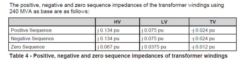
I've been working on symetrical components of transformers. I found a paper in which there is a table shows the impedance values of a 275/132/33 kV autotransformer. Is this a correct representation of impedance values ? Since the unit is in PU, isn't it supposed to be the same impedance value for both HV and LV side ? Why are there different positive sequence values for HV and LV side ? Is tranformer %Z impedance is the sum of positive sequence impedances of LV and HV sides ?
I've been working on symetrical components of transformers. I found a paper in which there is a table shows the impedance values of a 275/132/33 kV autotransformer. Is this a correct representation of impedance values ? Since the unit is in PU, isn't it supposed to be the same impedance value for both HV and LV side ? Why are there different positive sequence values for HV and LV side ? Is tranformer %Z impedance is the sum of positive sequence impedances of LV and HV sides ?