Distribution73
Electrical
- Mar 18, 2015
- 41
Hello,
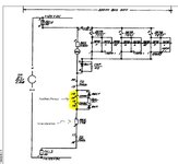
While reviewing drawings from an (old) existing substation, I have come across a number of tripping circuits where auxiliary relays (normally GE HFA51A type) are used in an arrangement I cannot quite understand.
These auxiliary relays are used in Busbar Diff and CBF circuits, where contacts of protection relays energize these auxiliary relays coils. The substation DC is 125Vdc, but the auxiliary tripping relay coils are 12Vdc rated. I understand this is something actually recommended by the aux relay manufacturer to increase speed of operation of the aux relay. What I dont understand is the use made of a resistor is series with the aux relay coils. I attach a circuit sample. I have seen IEEE recommendations (https://www.pes-psrc.org/kb/report/017.pdf) and this type of series resistor appears shunted by a NC contact of the auxiliary relay or a capacitor. I understand this being intended to allow full 125VDC excitation of the aux relay coil during a few milliseconds and then protect the coil once the aux relay has operated. In the substation however the resistor is permanently in series with the coil. Any feedback on the rationale of such arrangement (with a resistor permanently in series) would be greatly appreciated. It appears to me to be defeating the purpose of using a reduced DC rating coil.
On a similar note I have seen the coils been protected with diodes in parallel. These have resistor in series. Any feedback/source where I could learn what are the basis for the dimensioning of these parallel resistances would also be much appreciated.
Thank you in advance for the help.