tlewis3348
Mechanical
- Aug 23, 2017
- 31
I am modeling bolts with pretension loads, and I want to make sure that loads from other sources don't cause the total load isn't going to cause failure. My initial attempts were to just see if the peak stress in the bolt was higher the the failure criteria for the material. However, I quickly noticed that the standard loads (calculated based on information from the 29th edition of the Machinery's Handbook) produce stresses that are quite high. The reason for this is two-fold. First, it is because the pretension is calculated to be the following:
P = 75% × σPL × A
Where σPL is the proof load for the material (i.e. 85 ksi for SAE Grade 5 Bolts). In other words, this only guarantees that the average stress is below 75 percent of σPL, but the maximum stress may be significantly higher than that.
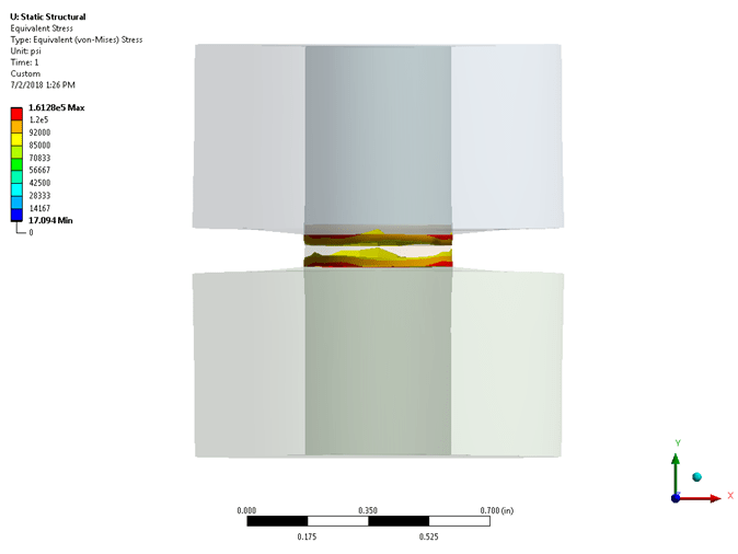
Secondly, it appears that the maximum stress in the bolts is where the shaft meets the head/nut (see image below).

This makes sense since there is a stress concentration at that location in my bolts, but this stress concentration isn't present in reality. Real bolts have a radius between their shaft and the head, and the geometry near the nut is obviously significantly different.
Therefore, it seems like the value I should be looking at for my failure criteria is the average stress at the cross section where the pretension is defined. However, I don't know how to get ANSYS to tell me what that stress value is. I've tried using a stress probe to give me the results I'm looking for, but I'm not sure what the "Solution Coordinate System" is. Furthermore, it appears that it will only return the maximum or minimum stress and not the average.
In short, I want to be able to get the average stress in a part at the XY plane of a specified coordinate system. Is that possible?
P.S. I should clarify that I am using "dumbell" bolts (i.e. a cylindrical shaft with two large "nuts" on either end) to represent the bolts in the model. I use these because they are modeled very easily, and seems to be about the best balance between model simplicity and computational intensity that I've seen.
P = 75% × σPL × A
Where σPL is the proof load for the material (i.e. 85 ksi for SAE Grade 5 Bolts). In other words, this only guarantees that the average stress is below 75 percent of σPL, but the maximum stress may be significantly higher than that.
Secondly, it appears that the maximum stress in the bolts is where the shaft meets the head/nut (see image below).

This makes sense since there is a stress concentration at that location in my bolts, but this stress concentration isn't present in reality. Real bolts have a radius between their shaft and the head, and the geometry near the nut is obviously significantly different.
Therefore, it seems like the value I should be looking at for my failure criteria is the average stress at the cross section where the pretension is defined. However, I don't know how to get ANSYS to tell me what that stress value is. I've tried using a stress probe to give me the results I'm looking for, but I'm not sure what the "Solution Coordinate System" is. Furthermore, it appears that it will only return the maximum or minimum stress and not the average.
In short, I want to be able to get the average stress in a part at the XY plane of a specified coordinate system. Is that possible?
P.S. I should clarify that I am using "dumbell" bolts (i.e. a cylindrical shaft with two large "nuts" on either end) to represent the bolts in the model. I use these because they are modeled very easily, and seems to be about the best balance between model simplicity and computational intensity that I've seen.


