Continue to Site

Eng-Tips is the largest engineering community on the Internet

Intelligent Work Forums for Engineering Professionals

  • Congratulations KootK on being selected by the Eng-Tips community for having the most helpful posts in the forums last week. Way to Go!

Axial Buckling about Non-Principal Axes

Status
Not open for further replies.

ajos6183

Structural
Sep 18, 2017
11
Hi all,

I have been having difficulties working out axial buckling about non-principal axes. I have come up with an example to illustrate my question (please see attached).
Suppose we have a simply supported column under compression only with a midpoint restraint about a non-principal axis. I am interested in finding the first buckling mode in the unrestrained non-principle axis of this column and after that the effective lengths about the principal axis.

Part 1: Finding P[sub]cr[/sub]
----------------------
My initial thought was that i can use P[sub]cr[/sub] = pi[sup]2[/sup] * E * I[sub]n[/sub] / L[sup]2[/sup] where I[sub]n[/sub] is the second moment of inertia about the non-principal axis.
For example, suppose that I[sub]x[/sub] = 42,082,500 mm[sup]4[/sup] and I[sub]y[/sub] = 7,382,500 mm[sup]4[/sup] and the section is rotated 45 degrees, then I[sub]n[/sub] = I[sub]x[/sub] - 0.5 * (I[sub]x[/sub] - I[sub]y[/sub]) * (1 - cos(2*45)) = 24,732,500 mm[sup]4[/sup]. I have confirmed this with a simple FE model in Strand7. (Note that subscripts x and y refer to the principle axes whereas n and p refer to the non-principle axes at 45 degrees)

However, this paper seems to say that i cannot do this in the case of a discrete restraint (my situation) and suggests instead an effective or quasi moment of inertia approach. Any thoughts on this?

Part 2: Finding effective lengths about the principal axes
---------------------------------------------------------------------
In this case, i know that L[sub]eff,n[/sub] is the full length of the column and that L[sub]eff,p[/sub] is half the full length. However, i am not sure how to convert these non-principal axes effective lengths to principle axes effective lengths (L[sub]eff,x[/sub] and L[sub]eff,y[/sub]) to be used in design. I look forward to your thoughts and help on this.

Thanks,
Anthony
 
 http://files.engineering.com/getfile.aspx?folder=c4c51b33-aed7-4605-96e7-6d193f6d85ce&file=Axial_Buckling_about_Non-Principal_Axes.pdf
Replies continue below

Recommended for you

1. I am unfamiliar with anyway to check buckling about a non-principal axis for a tube.

2. I did ask a similar question to AISC for angles. Since angles principal axis is not the same as their geometric axis I had the same question about the principal axis unbraced length. This was there response to my questions "Where a rigid lateral brace is connected to a compression member, the member can translate only in the direction perpendicular to the brace. Buckling about any rotated axis that is not perpendicular to the brace is restrained. Therefore, brace points in both the x-direction and the y-direction provide bracing in the z-direction."
 
I'm not sure if I'm missing something. What would be the mechanism for creating buckling that wouldn't occur on a principal axis?

The only thing I can think of is you are mixing up your coordinate system with the principal axes of the member. If that's the case then it's simple buckling. Ignore your global coordinate system, look at your member oriented flat. Then calculate buckling as usual.
 
There is no need to do this for a HSS member: it will never buckle about a non-geometric axis. If you want a complete example of manually checking a cross section that will buckle about a principal axis see: 'Tables for Equal Single Angles in Compression', AISC Engineering Journal, 2nd quarter 1991. The article is mostly tables....but it starts out with a complete (manual) calculation for a section.

By the way, the AISC article you link to doesn't work.

 
it sounds it me like you've got support on a non-principal axis. The column wants to buckle about it's weak axis. The question is how much support does the constraint provide in the weak axis ? if the column buckled on the weak axis how would the support ? if it's rigid then you see it creating a node for the buckle.

another day in paradise, or is paradise one day closer ?
 
Thanks Guys for all your responses,


gravityandinertia and WARose - if you look at my attachment, you will see that i have a restraint mid length of the column that is 45 degrees to the principle axes. Therefore, it is not possible for the first mode to be a pure principal axes buckle.


WARose - sorry for that, the link was working yesterday. I have attached it now.

 
 http://files.engineering.com/getfile.aspx?folder=c8d06207-5d4a-4a0d-b437-84c915907f8e&file=40_4_213.pdf
[blue](ajos6183)[/blue]

gravityandinertia and WARose - if you look at my attachment, you will see that i have a restraint mid length of the column that is 45 degrees to the principle axes. Therefore, it is not possible for the first mode to be a pure principal axes buckle.

Interesting problem (and I did not notice that restraint before).....I would still say this could be solved by buckling about the geometric axis(s). It would be a matter of resolving the bracing components in the X & Z direction.

However, in your OP you mentioned you had done a "FE model in Strand7". Is it showing such a unusual buckling mode?
 
Strand7 showed a buckle about the geometric axis, however, i was still a bit concerned given what the AISC article talked about.

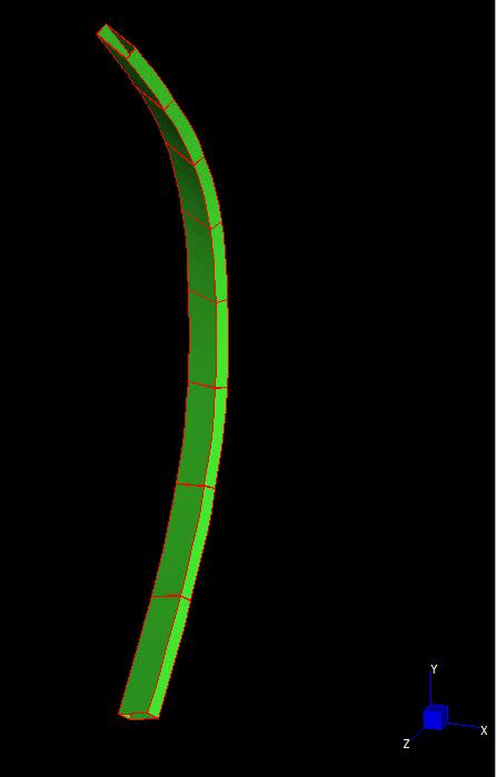
Capture3_qqolzd.jpg
 
Should buckle about the non-principal axis - my own quick little Strand7 model confirms this and the buckling loads using In check out. Quick scan of the paper - looks like the effective moment of area is only relevant for non-doubly-symmetric sections- if Ixy = 0, Ieff = Iy.
 
But isn't Ixy =0 only when it is aligned with the principal axes? I would have thought Ixy would equal 0.5 * (Ix -Iy) when the section is rotated at 45 degrees.
 
To be nearer to theoretically correct, I think that you do have to consider the effective moment of inertia described in the paper. My understanding of things, in the context of your problem, is as follows:

1) You'll get a first mode buckling effect producing displacement along the Z-axis as intuition would suggest.

2) The first mode buckling will create a moment about the X-axis as the member translates along the Z-axis.

3) The moment about the X-axis will create a complementary moment about the Z-axis. Biaxial bending theory in action.

4) The moment about the Z-axis produces displacement about the X-axis, generating second mode buckling in that direction.

5) 1 + 4 = that compound buckling described in the paper.

The first mode component of the compound buckling (Z-Axis translation) is working at an effective length twice that of the second mode component so it's not surprising that the first mode dominates for many practical situations. In fact, you'd have to work pretty hard to contrive a situation where it would matter much. One example might be an L8x4 braced at mid-span against translation in the plane of the longer leg.

I like to debate structural engineering theory -- a lot. If I challenge you on something, know that I'm doing so because I respect your opinion enough to either change it or adopt it.
 
Thanks KootK, at step 3, the moment about the X-axis creates moments about both the major and minor principal axes. But does it create a moment about an orthogonal geometric axis? I wouldn't have thought that it will do that.

I am finding that i cannot pick it up in a linear buckling analysis.
I performed a linear buckling analysis on the Z section example that is shown in the AISC paper but i still got the lowest buckling mode to be at about 26 kips in the X-Z plane, instead of the reported 13 kips!
 
OP said:
Thanks KootK, at step 3, the moment about the X-axis creates moments about both the major and minor principal axes. But does it create a moment about an orthogonal geometric axis? I wouldn't have thought that it will do that.

It does indeed. Imagine the distribution of flexural stress on the section when it bends about the X-axis. The centers of compression and tension will be offset along the X-axis creating a moment about the Z-axis.

OP said:
I performed a linear buckling analysis on the Z section example that is shown in the AISC paper but i still got the lowest buckling mode to be at about 26 kips in the X-Z plane, instead of the reported 13 kips!

Based on the sketches you've posted before, it appears that you're using eight elements to represent the member? If so, that's only four per half span which may not be sufficient to capture the second mode influence.

I like to debate structural engineering theory -- a lot. If I challenge you on something, know that I'm doing so because I respect your opinion enough to either change it or adopt it.
 
It might also be worth investigating whether or not the elements that you're using to model the member are even capable of "seeing" the coupling between the two geometric axis moments. I would expect that to require discretization not just along the length of the member but, also, within the cross section itself. I don't know Strand7 from Adam though so take my comment with a grain of salt.

I like to debate structural engineering theory -- a lot. If I challenge you on something, know that I'm doing so because I respect your opinion enough to either change it or adopt it.
 
KootK said:
It does indeed. Imagine the distribution of flexural stress on the section when it bends about the X-axis. The centers of compression and tension will be offset along the X-axis creating a moment about the Z-axis.

I understand that bending about the X-axis will produce deflections in the X and Z axes. This allows me to merge steps 3 and 4 of what you described earlier.

We know that Mz=E*Iz*v''+E*Izx*u''. The only case where i expect that Mz to be non-zero is when there is a mid-restraint forcing E*Izx*u'' to be different from -E*Iz*v''.
So in the case of normal biaxial bending (no mid restraints), i expect a movement in the X axis but not a moment about the z-axis.
Am i correct in saying this? and was this what you explained to me before?

KootK said:
Based on the sketches you've posted before, it appears that you're using eight elements to represent the member? If so, that's only four per half span which may not be sufficient to capture the second mode influence.

I tried subdividing further just now and there is no change to my previous result. I also used 'Mastan2' to double check the results from 'Strand7' and they are identical. Any chance this could be a second order effect that is not captured in a linear buckling analysis? (although it doesn't look like it is)
 
I suspect that KootK might have nailed it with his comment It might also be worth investigating whether or not the elements that you're using to model the member are even capable of "seeing" the coupling between the two geometric axis moments.
 
Denial said:
I suspect that KootK might have nailed it with his comment It might also be worth investigating whether or not the elements that you're using to model the member are even capable of "seeing" the coupling between the two geometric axis moments.

Both programs implement the Euler-Bernoulli Theory. Any ideas on how i know if they consider this or not?
 
Denial said:
I suspect that KootK might have nailed it with his comment It might also be worth investigating whether or not the elements that you're using to model the member are even capable of "seeing" the coupling between the two geometric axis moments.

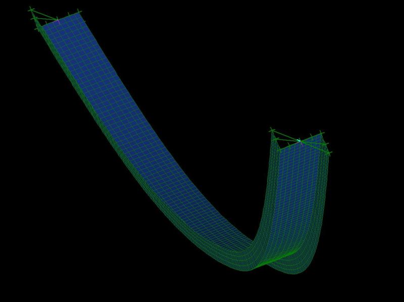
I just did a 2,700 node plate model and i cannot replicate the results of the paper. Instead i just get a geometric axis buckle with no coupling (at about 27 kips)!

Has anyone seen equations similar to the ones derived in the AISC paper in any other textbook or any other online resource?

Capture_slerzn.jpg
 
Status
Not open for further replies.

Part and Inventory Search

Sponsor