Eng-Tips is the largest engineering community on the Internet

Intelligent Work Forums for Engineering Professionals

Axial Load Ratio Under Seismic 1

Status
Not open for further replies.

ACS_1

Structural
Jul 15, 2020
8
0
0
AU
I have a question in regards to Axial load limit for vertical elements. It is for the latest Australian Standard but engineers outside Australia are welcomed to share your thoughts on this too.
Below is the clause.
3355_tonz8o.png


So basically when ductility is assumed, the axial load ratio should be limited to 0.2. It says structural walls but I think it applies to columns too. Now my question is, does this still apply to columns/walls on basement when the structural base is assumed to be on ground floor? My understanding is this ratio is to ensure the displacement capacity of columns/walls so it should not apply to the columns/walls in the basement as displacement won't be an issue for them. What do you think?
 
Replies continue below

Recommended for you

It is intended to apply to all walls. All gravity loadpaths need to comply under the seismic load cases.

The limit is there because walls generally have been shown to perform poorly under higher levels of axial load. For example there were a number of failures in NZ recent earthquakes, and you've adopted similar provisions introduced in NZ in response to the issues observed.

Also the actual axial load is quite hard to estimate accurately. Elongation in ductile hinges can mean additional axial load is generated as the wall is pushed upwards due to the elongation.

NZS3101 has the same limit, I'll post the commentary as it goes through the reasoning behind the limits which may prove helpful since you're still waiting for that mythical commentary to AS3600... One day....
 
OP said:
Now my question is, does this still apply to columns/walls on basement when the structural base is assumed to be on ground floor? My understanding is this ratio is to ensure the displacement capacity of columns/walls so it should not apply to the columns/walls in the basement as displacement won't be an issue for them. What do you think?

I think that it would depend on which basement walls and columns you're considering:

1) If it's a basement wall that is a continuation of an upper level wall, then the requirement probably ought to apply since the axial load developed in the upper wall to ensure it's displacement ductility needs to get transferred through the basement walls on it's way to the foundation without causing any buckling etc.

2) If it's a basement wall that is not a continuation of an upper level wall, and the wall layout is such that you've got stiff basement walls all around the perimeter, then I would say that the requirement would not apply since the walls would not be required to have great displacement capacity themselves nor would they receive such a demand from any walls above.

Does AU code allow you to have different mu's for different parts of the building or are you locked into a single mu for the whole thing? For walls like those that I've described in #2 above, the argument is basically that the ductility expectation for those walls would be minimal.
 

Were the failures in the basement as well? I get that walls (also columns IMO) has poor displacement performance when they are heavily loaded but for walls or columns under the structural base they are not supposed to resist much lateral loads and most importantly, the displacement shouldn't be an issue for them as the diaphragms are not like the upper floor that are at cantilevered but restrained by soil. So even if they are heavily loaded and has poor displacement capacities they are still okay under seismic.

But the ductile hinges generate at structural base, which is assumed to be at ground floor. With shotcrete walls all around, how will the hinge generate at elements at basement level?

Can you please post the snapshot of the NZS3101? Thank you.
 

They are discontinued from walls above. Most of they are the columns in carpark with transfer slab on top and I do have basement all around.

The Code doesn't mention local ductility. So I think global ductility for the whole structure is the case here (the Code is bit poorly written IMO). Put that aside, if I want to adopt different ductility for different elements, is the following procedure correct? Lets say if I adopt mu=1 for all, which means no ductility is assumed, and then I perform the analysis with original stiffness. And if there are walls that are in tension in any part of them under P-M (ie crack) then I reduce their stiffness and then re-analysis and keep this iteration until no more new walls will be cracked. And then I can design those non-cracked walls as non-ductile walls, like using singly reinforcement, ignoring axial load ratio etc?
 
Were the failures in the basement as well? I get that walls (also columns IMO) has poor displacement performance when they are heavily loaded but for walls or columns under the structural base they are not supposed to resist much lateral loads and most importantly, the displacement shouldn't be an issue for them as the diaphragms are not like the upper floor that are at cantilevered but restrained by soil. So even if they are heavily loaded and has poor displacement capacities they are still okay under seismic.

Lateral loads or displacement are not the real issue here, axial loads are the issue and the lack of confinement when compared to column detailing. It is an axial load limit, not a lateral load limit.

Most codes including AS and NZ codes allow you to go over the 0.2 or 0.3f'cAg limit if you provide column detailing and design according to the column requirements. This is driven by the comparatively relaxed approach to wall confinement when compared to columns and in general the unknowns in estimating wall axial loads with a degree of certainty.

Axial loads in the basement are likely higher than above the basement in critical areas, sure the load spreads out and you can demonstrate this and comply accordingly where required.

Here's the collected up bits and pieces from NZS3101 related to wall axial load limits:-

image_ypgoh0.png


Cracking and the reduction of stiffness is not a tension only mechanism as you infer (under the zero axial load line on a M-N interaction curve), if you exceed the cracking moment strength of the concrete alone under flexure the wall is cracked and a stiffness reduction is warranted for the seismic analysis.

And then I can design those non-cracked walls as non-ductile walls, like using singly reinforcement, ignoring axial load ratio etc?
No, this is definitely not the intent of the code writers. Cracking is not tied to ductility in that way. The global ductility factor has nothing to do with the local ductility demand in your structure. You could have a fully elastic building that requires ductile detailing by virtue of the plastic rotations/curvatures that are occurring. For example in a moment frame, if you have a shorter span, the curvature in this spans potential plastic hinge regions is higher, so more onerous detailing may apply irrespective of the demand being based on the same global ductility
 
Thanks Agent666. I understand this differently. I get that it is a axial load limit not a lateral load limit but the axial load limit is due to the poor displacement performance when the elements are heavily loaded. So when the displacement of a diaphragm is expected to be very small then it should be fine even these vertical elements that attached to it are heavily loaded. I don't get why we still need to consider this axial load limit when the drift of the element can be ignored?

I cannot find anywhere in AS3600-2018 states that seismic load on walls are allowed to exceeds 0.2fcAg when ductility is assumed. AS3600-2018 does require wall to be designed as column (or strut-tie) when any part of it is in tension and have the same confinement requirement as columns when concrete strength are over 50MPa and heavily loaded. But it doesn't mention that this detailing can override the axial load limit if mu>1 is assumed.

Thanks for the snapshot. Does NZS3101 allow you to use different mu for different elements? It doesn't cover anything regarding this in AS3600-2018.

When I said tension I didn't mean tension only. I meant part of the walls/columns are in tension. ie. tensile stress develops under P-M and exceed concrete tensile strength -> concrete cracks.

So how do you adopt different mu to different elements? Lets say, I want to see if some walls can be designed as non-ductile, how do you know whether it is okay to do so without performing displacement-based seismic analysis?
 
Agent666 said:
Lateral loads or displacement are not the real issue here, axial loads are the issue and the lack of confinement when compared to column detailing. It is an axial load limit, not a lateral load limit.

In reviewing the code provisions that you graciously shared, it seems pretty apparent to me that everything shaded in green below is about axial loads that have been induced by wall curvatures that are a product of lateral loads. Consider the language used: "in-plane", "compression zone", "curvature ductilities", "boundary zone", "plastic regions", "opening up of flexural cracks", "flexural and torsional stiffness".

Based on what I've reviewed so far, I'd say that everything shaded in green below most definitively is speaking to actions associated with the anticipated / required lateral displacement of the building which, I believe, is OP's argument. This must just be a semantic misunderstanding.

The only ambiguous provision would seem to be 11.3.1.6 but even that mentions wall ductility in the commentary. If that's not a wall ductility originating from a demand for lateral displacement capacity in the wall, what is it? Demand due to the walls own inertia or vertical seismic acceleration?

C01_cs287w.jpg
 
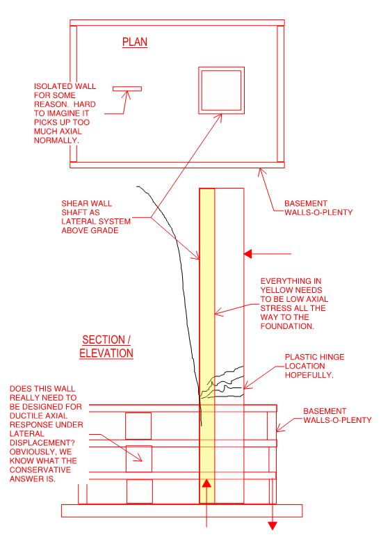
I do agree the axial limits are in part due to ultimately being about curvature and poor behaviour under seismic loading of walls with larger axial loads, what I was perhaps failing at explaining is the axial load limit isn't purely about seismic only. It applies everywhere in NZ code for walls and especially so under gravity only loading.

In the NZ standard at least the axial load limit applies to all load cases for walls, ULS gravity even (1.2G+1.5Q, 1.35G, etc). It is not limited to seismic cases only; it applies to all load cases. I cannot say if the AS standard has the same intent, but there seems to be a lot of stuff that is similar in the NZ intent in the 2018 version. I believe it also directs you to design to NZS3101 for proper ductile design. Rapt can probably expand on the thinking of the code committee if he reads this, and what the exact intent is.

So basically my understanding is the limit is not only about some roundabout way of addressing poor wall performance under seismic. It is also about axial loads being wholesale limited to the 0.3f'cAg limit irrespective of the load case. In a seismic sense in coupled wall systems which undergo little curvature, they can for example generate large coupled axial forces.

We had several walls fail in the 2011 earthquakes in Christchurch due to poor confinement combined with larger than expected axial loads being developed compared with the original design. This is the basis for the changes in our standard and the introduction of the similar provisions in your standard.

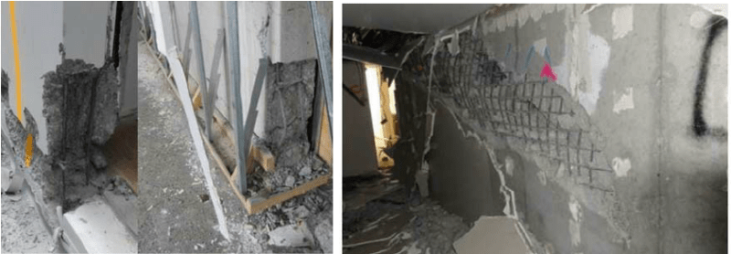
For example, the right image below occurred in the Chancellor Hotel I believe, I believe it was attributed to axial loads due to overstrength axial loads and poor confinement, larger than anticipated axial loads developed due to an albeit unusual structural system involving a transfer structure. They reckon if the shaking had gone on for slightly longer the entire structure would have collapsed with a significant loss of life. But this is what the provisions are meant to protect against. Using walls to carry large axial gravity loads is what these provisions address, both gravity alone and seismic induced gravity loads irrespective of wall location: -

image_o5bvjc.png


In NZ at least in your basement you would still need to comply without the displacement issues irrespective. Your provisions come out of our same learnings as I understand it that our provisions were based on. The 2018 version of AS3600 took a large leap forward in bringing your design standard forward to what is considered more or less current best practice based on the current state of research into wall behaviour. Some of the stuff that was newly introduced to AS standard relating to seismic design has been in the standards here in some form or another since the early 1970's, so you can certainly leverage a lot of the similar approaches and so forth from NZ for seismic design in Australia as there is a lot of commonality.

A common theme that seems to come through here on Engtips from Australian designers is one of how do we avoid these new provisions because they are so onerous, change the way we designed in the past, etc, etc. We get that here to, but we know the real consequences and loss of life that can occur when designers take shortcuts like this and argue semantics around code provisions and the like just to avoid doing the obvious.
 
ACS_1, have a read of this thread as it may offer some additional insight
It goes through the whole gambit of wall design to AS3600. Rapt who commented in that thread was/is on the AS3600 code committee.

Kootk, regarding the point you noted on CL 11.3.1.6, 'nominally ductile walls' is a classification for any walls that have curvatures lower than a prescribed ductile limit. So it's basically defining a subset of every wall that isn't classified as requiring a higher level of detailing. There are 3 limits, Nominally ductile, Limited Ductile, Ductile. Each classification level has a prescribed set of detailing provisions. Nominally ductile walls may see some limited amount of ductility, or none there is no further differentiation (like perhaps in the case of basement walls depending on the configuration), but they would still be required to be detailed to the same provisions that would afford them some modicum of ductile response if that makes sense.
 
cristiano.ronaldo said:
The larger the axial load, the smaller the ductility.

No doubt. But the question is really whether a wall of a the sort being considered in this thread needs ductility (refer to my previous sketch). I would argue that it does not and, code parsing aside, I've seen no rational explanation so far for why it should other than, perhaps, "isn't more ductility always better?". More ductility is always better, of course, but practical engineering isn't about what is best. Rather, it is about what is economical and good enough.

Agent666 said:
A common theme that seems to come through here on Engtips from Australian designers is one of how do we avoid these new provisions because they are so onerous, change the way we designed in the past, etc, etc.

I have some sympathy for the AU perspective. In Canada, it seems to work like this:

1) Our rock star seismic professors, who are quite incapable of contemplating anything less than Richter 9.0, come up with great ideas about how to deal with Richter 9.0.

2) Because we respect our rock stars, we agree to put their provisions into our codes without very much coordination with the other sections of the codes that aren't speaking to Richter 9.0.

3) We wind up with a bunch of impractical provisions in our codes that are semantically tight as drums but don't make sense to any discerning engineer when not considering Richter 9.0. This generates neither trust nor compliance.

It's been resolved now but, for a time, certain conditions would result in an R=1.0 / Capacity design for shear a wall foundation out in the Canadian prairies where seismic demand is about as low as it gets. Your elevator mat foundation would have to be bigger than the footprint of your building unless you made some sketchy recourse to foundation rocking.

 
I will say, however, that I don't think that the 0.3 requirement is even all that onerous. I'd consider that a pretty well loaded wall, even in the gravity only condition.
 
We've had the opposite situation once upon a time, adequate proven provisions that dealt quite nicely with a certain issue, then for one code cycle they were relaxed quite a lot, then realising their mistake reintroduced them next time round in a near identical form to previously.

Then along came an earthquake exposing this venerability in buildings built over this time and we are back to retrofitting this shortfall or living with it, but in the interim arguably over a hundred lives snuffed out because of this contributary issue in our 2011 Christchurch earthquakes. Once upon a time we had the attitude that earthquakes never happen in Christchurch because of its relatively low seismicity, well that ended well....

I very much think you need to be reading between the lines with codes because it is very rare that a practicing consulting engineer who is a designer would be sitting on a code committee (It does happen, but the exception to the rule maybe). They are the bare minimum requirement after all and small improvements in your detailing. Actually thinking about load paths rather than plugging and chugging code formulas can go a long way towards increasing performance if you understand the issues being addressed and where your loads want to and do go rather than hitting a button in some software and blindly accepting exactly what the programmer said to be true.


I will say, however, that I don't think that the 0.3 requirement is even all that onerous. I'd consider that a pretty well loaded wall, even in the gravity only condition.

When you have software designing things to 0.99 ratio anything is possible when engineering judgement is relinquished to the computer... [pc]
 
The main reason for limiting the compressive stress of compression member is to assure the compression member falls within the tension control region (below balanced design condition). A glance on P-M diagram will help to realize the concept. The 0.2 threshold must come from studies, or experiments. I remember a P/A ratio limit of 0.15, but couldn't find the background material.
 
Ron said:
Not load dependent.

Ron, I disagree with that statement as it pertains to reinforced concrete sections which are ebeing discussed here.

There is a well known link between the capacity for ductility of a reinforced concrete section and the applied axial load.

Cross section ductility is governed by the materials, their distribution, cross section shape and dimensions as well as the loads.

A moment curvature analysis will show this general trend with a general reduction in ductility under higher axial loads.

 
I agree with Ron. However, cristiano are not completely wrong if add the word "stress" after "axial load". It is a well known material property, that the higher the compressive stress a material can endure (higher strength), the more brittle/less ductile it is. Ductility can't be measured by force alone. For example, a large axial load on a 10' long column, with one square foot cross sectional area and an eccentricity, tends to be more likely fail in ductile mode, when compared to a ten square feet column with the load, length and eccentricity been held the same.
 
Status
Not open for further replies.
Back
Top