Continue to Site

Eng-Tips is the largest engineering community on the Internet

Intelligent Work Forums for Engineering Professionals

  • Congratulations KootK on being selected by the Eng-Tips community for having the most helpful posts in the forums last week. Way to Go!

Axially loaded steel column directly in footing (no pedestal, just bending rebar)

Status
Not open for further replies.

octagie

Civil/Environmental
Feb 20, 2019
18
Is there any particular consideration on having an axially loaded steel column (compression and tension) placed directly over a deep footing (1.6 m deep)? without either a pedestal or pedestal rebar inside the footing (embedded pedestal)? Appart from punching shear, is there any other consideration to consider that are not on codes? Anchor bolts will end deep with an end plate (they are 2 inches diameter), so i don't need any rebar parallel to the anchor bolts. Also, I don't need to confine the concrete, since the base plate is generous, so no stirrups forming an embedded pedestal. So the footing will have just bending rebar (bottom and top). All my calculations are OK (pull out, punching shear, endplate thickness, etc.), it is just I haven't seen similar things with big axial loads. Any comments?
 
Replies continue below

Recommended for you

I think this method lacks popularity due to:
1) It's not a simple matter to hold the steel column firmly/precisely in place during construction.
2) The stresses in the concrete block are not clear due to the interaction of soil pressure, flexural bending and shear force from column, thus the long term performance of this support.

It is odd to me that seems there are anchor bolts beneath the base plate. Is your pull out calculation based on the anchorage strength, or the base plate projections? Also, when you check punching shear, what was the depth in the calculation - over all depth of the footing, or concrete below the base plate only? Can you show a sketch?
 
I agree that a sketch would be helpful. When I read your post, it sounds like a traditional steel column with base plate anchored to the top of a giant block of concrete. I think (but may be wrong) that retired13 is interpreting this as a directly embedded steel post in concrete. A sketch will clear up any misunderstanding.

You say it's 1.6m deep - how wide/long? You may want to look at it as plain concrete - that would probably simplify a lot of what you're trying to do. Also, be careful about mass concrete effects. That's a lot of concrete and you'll have issues dissipating the heat of hydration as it cures.
 
phamENG,

Yes. I misunderstood the situation. Thanks for pointing out.
 
octagie said:
Is there any particular consideration on having an axially loaded steel column (compression and tension) placed directly over a deep footing (1.6 m deep)? without either a pedestal or pedestal rebar inside the footing (embedded pedestal)? Appart from punching shear, is there any other consideration to consider that are not on codes? Anchor bolts will end deep with an end plate (they are 2 inches diameter), so i don't need any rebar parallel to the anchor bolts. Also, I don't need to confine the concrete, since the base plate is generous, so no stirrups forming an embedded pedestal. So the footing will have just bending rebar (bottom and top). All my calculations are OK (pull out, punching shear, endplate thickness, etc.), it is just I haven't seen similar things with big axial loads. Any comments?

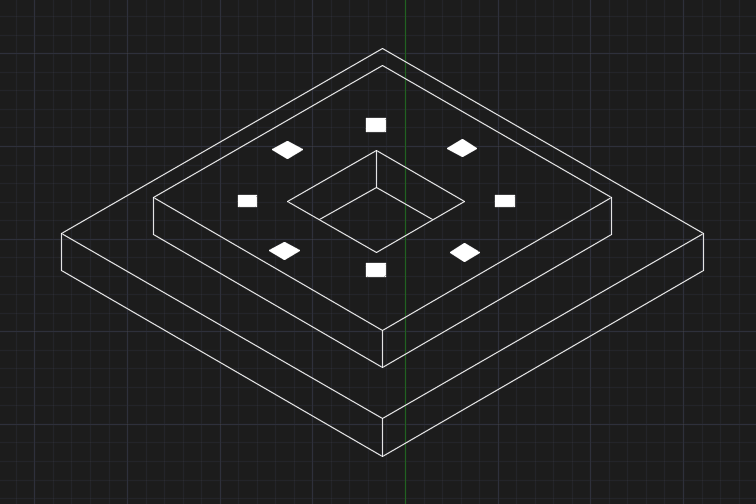
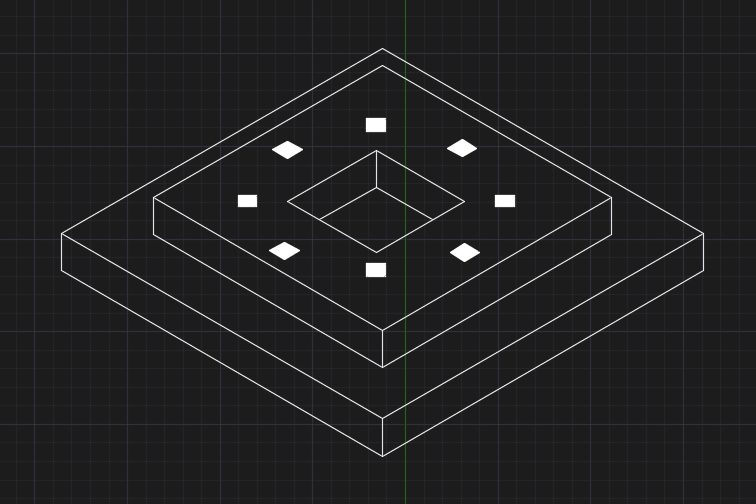
Something like this (see attachment)?
 
 https://files.engineering.com/getfile.aspx?folder=7339bb29-abe9-498a-a193-fe25083d38c5&file=140_v2.jpg
Is the steel column extended below grade?
 
kingnero,

Is that photo shows a stack foundation?
 
I've successfully used such base plate to concrete foundation (sans pedestal) connections in the interior of retail facilities. Other than the general capacity of the connection, have a strategy in mind to address corrosion where/if the connection is below grade. Good drainage, slab on grade encasement, painting the bottom of the column with bituminous stuff... Things like that.
 
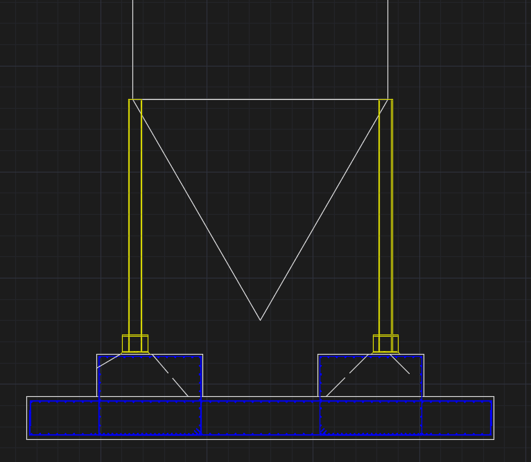
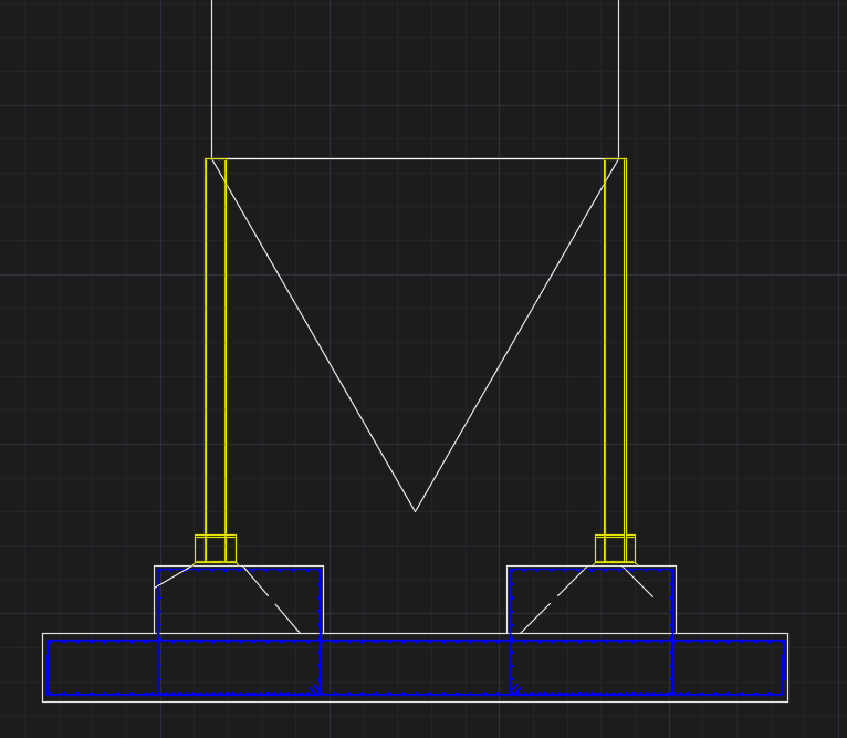
Sorry, attached sketches. Footing is 10 m wide, and stepped (0.8 m + 0.8 m). Seismic is controlling the weight of the footing (impulsive mass is big, is is a water tank). Axial loads are 153 tonf compressive, base plate is 60cm x 40 cm, and 78 tonf uplift taken by 6 1+1/2 inch A36 bolts, with an endplate deep), I performed a winkler foundation analysis but I find results unreliable, anyhow, flexure is not my concern (minimum rebar should suffice by far) my most serious doubt is whether or not I should place some sort of localized reinforcement (embedded pedestal rebar) to 1. confine the concrete and 2. to help take the tension bolts. My calculations say they are not needed (bolts go full depth with the endplate) and also constructively its a serious headache, but is looks like its missing something without it.
 
 https://files.engineering.com/getfile.aspx?folder=2cace6d9-20da-4fc1-b367-ca301cf3c0d9&file=Sketches.rar
By looking on the "cut.png", it looks like the critical shear section is beyond the footing for both columns on outboard side. I think it is a weakness you need to pay attention to.
 
BA,

Your computer shall ask your permission to install an Un-zip file to extract the zipped files for view. Try again, or just install any un-zip program that is capable of open ".rar" file format.
 
retired13,

My computer did not ask permission to install anything. I loaded winzip but it didn't work properly, so I will just pass on this thread. Thanks anyway.

BA
 
Me too, BAretired. My computer wants me to install an app, doesn't say what one, so I will pass. But what the OP described sounds perfectly normal to me.
 
BA,

Don't give up so early. Try this one (that was asked to installed on my pc) that opens .rar zip file.

Link
 
Hang on...I think it worked:

3d_xlc0kk.png


Cut_f57ycj.png


Yes indeed...thanks retired13.

BA
 
Here are the images in question.

Cut_xddly0.png


3d_qowyi1.png


ETA: too slow for these guys.

AETA: FWIW - I used an online extractor at extract.me (not linked on purpose)
 
Thanks azcats, but I finally got the images more by luck than good management. I get 21 days of free use, then I'm supposed to pay for it. Not so sure about that.

Now that I see the image, I will have to think about it. At the moment I don't really see the problem mentioned by retired13.

EDIT: It might be better if the foundation could be rotated 22.5[sup]o[/sup] relative to the columns.

BA
 
BA,

On the 2nd picture of your download, the columns are off foundation center and look like quite close to the outboard footing edges. Although the anchor pull out check is fine, don't you think some vertical bars are warrant?


ADD: BA, don't pay for the zip file you have downloaded. There are many freeware online, here is another one, free and looked powerful.
 
Status
Not open for further replies.

Part and Inventory Search

Sponsor