Continue to Site

Eng-Tips is the largest engineering community on the Internet

Intelligent Work Forums for Engineering Professionals

  • Congratulations KootK on being selected by the Eng-Tips community for having the most helpful posts in the forums last week. Way to Go!

Axis of a [very short] cylinder as DATUM 3

Status
Not open for further replies.

AqUa3o

Aerospace
Nov 22, 2019
1
Hi all!

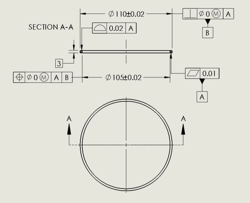
Let's suppose that I have the square-section metal ring below.
Esempio_nvraxi.jpg


My goal is to be sure that the axis of the inner cylinder is concentric with respect to the axis of the outer cylinder, and that both axes are perpendicular to the datum A.

I thought the attached drawing was correct, but then I realized that the axis of cylinders so "short" is too influenced by very small variations of the "diameter" surface.
Once in the measurement department of my factory, I was told that "pulling out" an axis from cylinders so short, using a CMM, is practically impossible.
But then, since we do not want to use gauges, how could I "get around" the problem?

Any suggestions would be welcome, I've been thinking about it for a while but I can't find a solution.

Thanks in advance,
F.
 
Replies continue below

Recommended for you

The UAME axis of both ID/OD would be difficult to extract reliably due to the aforementioned reasons. Since you have both diameters referenced at MMC and your flat face A is primary, then control of the ID/OD as well as simulation of B should only require use of the RAME which will be far less sensitive to variations in the surface and easier to extract. The caveat is they would have to use the surface interpretation for the MMC control as the axis interpretation requires measurement of the UAME.

Is another measurement device possible? An optical comparator should make short work of this.
 
To avoid derivation of an axis from a short feature that may result in measurement issues as you described, profile tolerance specification instead of position can be considered. Perhaps somewhat unusual for a control intended to ensure centered location and orientation of features of size, but I think it should do the job without introducing CMM issues.
 
AqUa3o,

I assume this is dimensioned in millimetres. Is it ASME Y14.5?

The big problem I would have inspecting your part is that it is flexible. Even the wand of your CMM will bend this thing to the point that you can establish those very precise tolerances. If I needed to inspect a bunch of these things, I would make a fixture. The fixture would have an inside diameter feature 110.02mm. This would be go-gauge. I could use shims to verify the LMB/C condition. There would be an outside diameter feature 104.98mm. This would be another go-gauge. Again, I could use shims to verify LMB/C. I would measure from the fixture OD to the OD of the ring to verify the positional tolerance at the MMB/C of the ID.

How do you figure out which face is datum[ ]A?

It has been a long time since I have played with an optical comparator. Could you set this up on one?

--
JHG
 
A first glance....make the datum feature "higher" by placing many known radial thickness "spacers" against the OD that are high enough to allow good contact of CMM probe. Not conclusive but might be the best approach for measurement.

Certified Sr. GD&T Professional
 
Status
Not open for further replies.

Part and Inventory Search

Sponsor