Eng-Tips is the largest engineering community on the Internet

Intelligent Work Forums for Engineering Professionals

Axle failure, thoughts 8

4130 metalworks

Mechanical
Sep 22, 2024
3
0
0
AU
20240926_211622_bquzkm.jpg
20240926_211609_vgjrff.jpg
20240926_211704_uuvgln.jpg


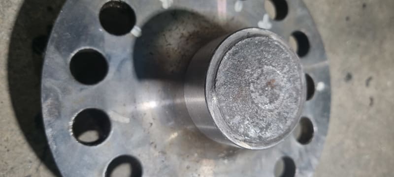
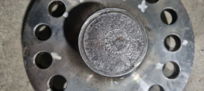
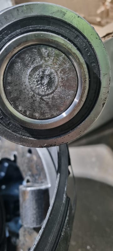
Hi, I'd like to get the groups thoughts on why this axle shaft failed and how to best go about testing the rest of them. The shaft is heat treated 4140, from machining the splines the hardness seems to be the outer 2-3mm.
Unfortunately I don't have much information from the manufacturer to go with

The vehicle is reasonably heavy but low powered and was travelling at speed when this happened

Thanks in advance for any help
 
Replies continue below

Recommended for you

Op
From the picture it appears to be a brittle fracture.
Have the other axels NDT mag for indications

Take this axel and send to independent met lab, verify the following.
Material, heat treat condition hardness, tensile test, charpy test
Inspect microstructure.
Electron microscope for hydrogen embritalment.
Pull Material certs, and heat treat certs, and chemical treatment, such as temper etch. Make sure it was post bake properly
Incorrect heat treat procedure will Crack mayerial.
 
Looks like a fatigue fracture that looks to have originated at a stress concentration where the shaft diameter changed abruptly. Usually I would look at the way the wheel/axle was loaded, but that's not presented.

Given how little material remained at the final stage as seen by the small circle in the middle, the material seems sufficiently strong. Maybe it was overloaded some time to bend the axle or maybe it's been running overloaded for a long time, or maybe the radius at the change in diameter is just too small.
 
Dave
Yes but I don't see a initiated Crack then
a catastrophic failure. If it was a over load , there would of been a Crack initiated. Or am I wrong.
 
On the failure surface, is there any part that appears to be smooth or is the entire surface only composed of a grainy surface?

-----*****-----
So strange to see the singularity approaching while the entire planet is rapidly turning into a hellscape. -John Coates

-Dik
 
It broke right where the radius of the inner bearing race met the shaft the shaft appears to have been of a straight diameter at that point. There is a step in diameters where the shaft appears to have butted against the eating but I don't see anything to indicate that the failure initiated at that step. It's possible that the shaft wasn't properly seated against the bearing which led to a fatigue failure.
 
20240928_105913_je7gwm.jpg


Our thoughts were the radius between the step up is insufficient. But we dismissed that as its almost exactly the same as the different brand replacement
 
The failure does not appear to have initiated in the radius on the shaft. It appears to have initiated at the point of contact between the bearing race and shaft. If the shaft were property seated against the bearing race there should be no bending where the shaft failed. I don't think the shaft was seated properly against the bearing race. This may have been an improper assembly and there was no defect in the part.
 
Shafts are a pita to manufacture.
Keeping shafts straight and concentric
Is not simple. The whole manufacturing is an art and skill.
These are my thoughts.
How concentric and straight were the shafts before heat treating.
And where the shafts staighten.
During and after heat treat were the shafts straighten .
Were the shafts stress relieved ti remove stresses.
Straightening can cause internal stresses and defects.
If the shafts have moment while in use.
And does have proper support. Then I would say yes over load and torsional stress. But I will stick with brittle fracture. And wait for OP to test.
 
The fracture in the bearing side appears to be at the same depth as the chamfer that is there to clear the radius. I expect it was fully seated.

As long as there is a chamfer there will be bending where the chamfer ends. Perhaps easing the edge of the chamfer would help. It's still a very short stub of that small diameter so the difference in bending is small.

There could be a photo taken from the side of both parts - don't allow them to touch or it will damage microscopic evidence.
 
Fatigue is a brittle fracture rather than a plastic fracture. It proceeds along grain boundaries. Unlike overload fracture, fatigue fracture will show multiple areas the broke - the outside and the inside of that ring for example. Fatigue is most always at right angles to the direction of loading; overload fracture tends to follow a 45º path at some point of the break. Torsion failures tend to be along a 45º degree spiral.
 
Google quote:
Brittle fracture is a sudden, rapid cracking of a material under stress. It can be caused by several factors, including:

Stress: High residual or applied stress, or cyclic loading (fatigue)

Temperature: Low temperatures, or temperatures below the glass transition temperature for the material

Grain size: Reduced grain size

Cracks: The presence of a crack-like flaw or defect within the material

Strain rate: High strain rates, such as those caused by impact

Material: Low fracture toughness, metallurgical degradation, or steel contaminants

Section size: High material thickness
 
The clear inner area seem to indicate a gradual crack or failure then a final sudden failure.

Need more examination for sure to see whether that's a fatigue crack or two failure back to back.

Remember - More details = better answers
Also: If you get a response it's polite to respond to it.
 

It usually initiates from a flat smooth part of the initial failure.

-----*****-----
So strange to see the singularity approaching while the entire planet is rapidly turning into a hellscape. -John Coates

-Dik
 
the fractured surface exhibits many concentric circles coupled with a "fiber" small circle at the center. In addition, there is no obvious fracture origin. This all suggests it is a rotational fatigue fracture under high stress conditions along the end edge of shaft. The smaller radius could introduce significant stress to reduce a fatigue life.
 
The failure point where the shaft diameter has stepped down is typical and expected in shaft failures, especially fatigue. This is the point where stress is highest, and not in the corner itself. Visually it looks like fatigue with multiple ratchet marks at5 the OD indicating multiple origins. Again not surprising. First thing you should do is characterize the fracture surface in an SEM to determine likely failure mode. You should be able to confirm dimple ductile rupture from overload (as it looks) in the center.
 
The high surface hardness, possibly caused by surface hardening techniques like quenching or induction heating, may result in a relatively softer core. A large hardness gradient can lead to brittle fracture under high-stress conditions. This is especially true when the component is subjected to heavy loads or strong impacts, as the hard and brittle surface is more likely to develop cracks that can propagate throughout the shaft.

 
How long was the shaft in service?
I'm still unclear whether the fracture surface propagated from a groove machined in the shaft.

Any micromotion of the shaft within the bearing at the edge near the shaft shoulder would cause fretting. The endurance strength of a fretted surface is mighty low.

I think the bearing would need to be clamped HARD against the shaft shoulder in order to take over as part of the bending load path.

Is the picture of an un-broken shaft the new replacement shaft?
Is the mottled gray surface from shot-peening ? That could provide be a BIG improvement.
The radius/fillet profile on the lower side of the shaft looks uneven.
A uniform, well blended radius is required.
 
 https://files.engineering.com/getfile.aspx?folder=82f2ca32-94ce-442c-be59-a810c8ddc7df&file=fretting_and_corrosion_effect_on_endurance_limit_and_fatigue_strength_.png
Thank you everyone for the insights into possible reasons this shaft failed. Unfortunately due to costs involved in testing, I won't be able to give a definitive reason. I didn't think testing was so expensive (quotes came in between $6500-7000aud)

Between paying for repairs and the original manufacturer stone walling me this isn't feasible right now
 
Back
Top