Killstadogg
Mechanical
- Aug 23, 2012
- 8
Hi all,
I'm designing an ASME B31.1-2012 system that operates at 10,000 psig. After considering possible fluid transients I selected a design pressure of 12,000 psig. I've never done anything at this high of a pressure before so it's been sort of a learning curve figuring out what fittings, hoses and tubing are available. The system is essentially a custom high pressure spray apparatus. I realize that B31.1 isn't really the code to use for this application but the client requires it. End of story there.
However, to get to the point here, I'm finding out that even though manufacturers such as Parker and Spir Star make products that are rated to 15,000 psig and beyond, I'm finding that per ASME B31.1 straight pipe minimum wall thickness calculations that these products would experience yielding.
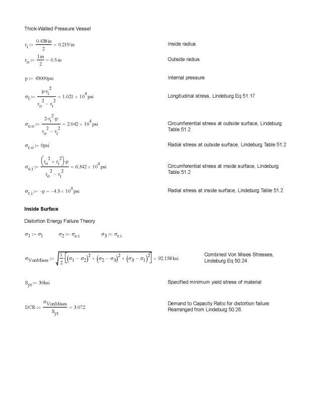
The minimum wall thickness per ASME B31.1 para 104.1.2 essentially determines the minimum allowable wall thickness based upon the stress at the inner pipe wall. By using thick-walled pressure calcs, I'm finding that the stresses present in the inner pipe wall of off-the-shelf components are above the yield strength of the specified material. However the stresses present at the outer pipe wall are below yield strength.
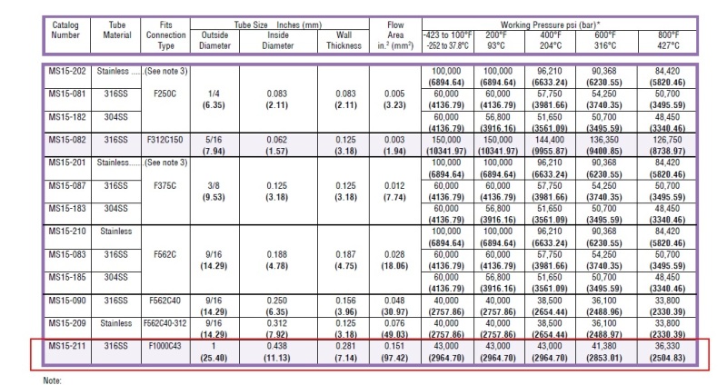
For example let's look at this Parker MS15-211 stainless steel tubing. They claim the max working pressure is 43,000 psig, so we'll use that as the design pressure. The material is 316 SS, which has a specified minimum yield of 30 ksi. We'll just assume this is the maximum allowable stress before yielding - which normally we'd use the allowable stress value given in ASME B31.1, Appendix A. The OD of the tubing is 1 inch, so using B31.1 eq 7, and we get tm = (43000*1)/(2*(30000 + 43000*0.305)) = 0.499 in
where:
y = 0.438/(0.438+1.0) = 0.305

This result is essentially telling us that the tube is not acceptable at this pressure with this yield strength (OD - 2*tm) = very small.
However, the ultimate tensile strength is not reached because if we plug in 70 ksi into B31.1 eq 7 we get tm=0.259, therefore the ID could be as large as 0.48 inches.
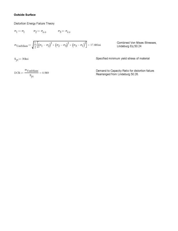
The major caveat here is that this high of a yield stess is only present at the innermost surface of the pressure boundary. Per thick-walled pressure vessel calcs, and the distortion energy failure theory, yielding occurs at the inside surface of the pressure boundary, but not the outside surface.


So, to finally get to my question here: is it reasonable to justify the components are acceptable for use in a B31.1 system because yielding doesn't occur at the outside surface and that the ultimate tensile stress is not reached anywhere within the component wall? The calculations show that 'yielding' occurs at the inside surface, however it doesn't seem that the 'yielding' metal would have anywhere to move to, considering the other material is staying put. Perhaps this material essentially strain-hardens. Considering the components that Parker and other manufactures make seem to do just fine in regular industry, I personally don't see a problem. I really just need a solid argument to justify components per B31.1 para 104.7.2, which requires "... calculations consistent with the design criteria of this code".
Any and all advice is more than welcome!
Thanks
I'm designing an ASME B31.1-2012 system that operates at 10,000 psig. After considering possible fluid transients I selected a design pressure of 12,000 psig. I've never done anything at this high of a pressure before so it's been sort of a learning curve figuring out what fittings, hoses and tubing are available. The system is essentially a custom high pressure spray apparatus. I realize that B31.1 isn't really the code to use for this application but the client requires it. End of story there.
However, to get to the point here, I'm finding out that even though manufacturers such as Parker and Spir Star make products that are rated to 15,000 psig and beyond, I'm finding that per ASME B31.1 straight pipe minimum wall thickness calculations that these products would experience yielding.
The minimum wall thickness per ASME B31.1 para 104.1.2 essentially determines the minimum allowable wall thickness based upon the stress at the inner pipe wall. By using thick-walled pressure calcs, I'm finding that the stresses present in the inner pipe wall of off-the-shelf components are above the yield strength of the specified material. However the stresses present at the outer pipe wall are below yield strength.
For example let's look at this Parker MS15-211 stainless steel tubing. They claim the max working pressure is 43,000 psig, so we'll use that as the design pressure. The material is 316 SS, which has a specified minimum yield of 30 ksi. We'll just assume this is the maximum allowable stress before yielding - which normally we'd use the allowable stress value given in ASME B31.1, Appendix A. The OD of the tubing is 1 inch, so using B31.1 eq 7, and we get tm = (43000*1)/(2*(30000 + 43000*0.305)) = 0.499 in
where:
y = 0.438/(0.438+1.0) = 0.305

This result is essentially telling us that the tube is not acceptable at this pressure with this yield strength (OD - 2*tm) = very small.
However, the ultimate tensile strength is not reached because if we plug in 70 ksi into B31.1 eq 7 we get tm=0.259, therefore the ID could be as large as 0.48 inches.
The major caveat here is that this high of a yield stess is only present at the innermost surface of the pressure boundary. Per thick-walled pressure vessel calcs, and the distortion energy failure theory, yielding occurs at the inside surface of the pressure boundary, but not the outside surface.


So, to finally get to my question here: is it reasonable to justify the components are acceptable for use in a B31.1 system because yielding doesn't occur at the outside surface and that the ultimate tensile stress is not reached anywhere within the component wall? The calculations show that 'yielding' occurs at the inside surface, however it doesn't seem that the 'yielding' metal would have anywhere to move to, considering the other material is staying put. Perhaps this material essentially strain-hardens. Considering the components that Parker and other manufactures make seem to do just fine in regular industry, I personally don't see a problem. I really just need a solid argument to justify components per B31.1 para 104.7.2, which requires "... calculations consistent with the design criteria of this code".
Any and all advice is more than welcome!
Thanks
