Eng-Tips is the largest engineering community on the Internet

Intelligent Work Forums for Engineering Professionals

  • Congratulations waross on being selected by the Tek-Tips community for having the most helpful posts in the forums last week. Way to Go!

Balancing a Slider-Crank Mechanism? 5

Status
Not open for further replies.

Helepolis

Mechanical
Dec 13, 2015
198
0
0
IL
Hi all,

I'm working on a design of a reciprocating mechanism (Slider-Crank) and trying to figure how to balance it.

So far all i have found are scientific papers but they don't help me much as i don't care about the theory but rather looking for the final parametric formula(s), into which I can plug in my variables and get an answer.
I might be over optimistic about finding the "easy way" (a complete formula(s)), but I do remember something from the Theory of Mechanisms course that there is a rather straight forward calculation for finding out the balancing force (I might be wrong but I cant find my notebook to confirm it).


Thanks,
SD
 
Replies continue below

Recommended for you

Could you calculate the location of the CG at points throughout the stroke and add/remove mass to prevent it from moving significantly? I don't think this would eliminate all forms of vibration but it may be enough for your mechanism though. Maybe there is some similar quick calc you can do for moments as well.
 
hendersdc said:
Could you calculate the location of the CG at points throughout the stroke and add/remove mass to prevent it from moving significantly? I don't think this would eliminate all forms of vibration but it may be enough for your mechanism though. Maybe there is some similar quick calc you can do for moments as well.
In general I can, I can pull the CG locations (of each component and the combined CG) from the CAD software, but I'm looking for a less "trial and error" way of getting the mass and distance right.
As a general note, from what i have learned so far even with the correct calc of the counterweight there will always be vibrations (due to the components of the counterweight CG vector), but those will be acceptable.

Tmoose said:
Thru what angle does the slider crank rotate ?

many complete rotations as 3600 rpm ?
The mechanism will operate at a much slower rpm than 3600, more like 4Hz (240 rpm) max.
I'm not sure i understood the angle question.

Strong said:
Perhaps review of single cylinder engine balancing could be of value.

Walt
Thanks for the suggestion, but I've already done some googling (and binging [smile]) but all i can fined is "useless" info, with either dry info on what it's all about or a "heavy" research paper with some hardcore theoretical math.
I don't need neither, just looking for the final formula(s) so i can calculate the parameters I need.

As I said, I'm 90% sure that there is a "simple" way of doing the math (at least this is what I think I remember from the Theory of mechanisms course).
 
From that single-cylinder-engine situation, what you should have gleaned out of it is that "there is no simple answer".

The rotating part of the crankshaft and the (roughly) half of the connecting rod whose end is attached to the crank, can be balanced with a crank counterweight such that the center of gravity of the combined mechanism is at the center of the shaft. BUT ... The reciprocating component of the mechanism, and the (roughly) half of the connecting-rod whose end is attached to the piston (slider), will not be counterbalanced at all.

You could of course make the counterweights heavier so that the center of gravity in the direction of reciprocating motion is stationary (ish - see note below) but then you will have a strong side-to-side out-of-balance because the overweight counterweights are not offset in that direction. (Note: The swinging motion of the con-rod imposes a twice-crank-speed vibration component. It's complicated.)

In automobile practice ... this is the reason for multi-cylinder engines, with cylinder and crankshaft arrangements laid out so that one piston's and crank-weight's motions are offset by another one that's either pointing in a different direction or acting in a different phase or both.

I have a single-cylinder motorcycle. It uses a counterbalance shaft, spinning at crankshaft speed in the opposite direction, with a counterweight which, when combined with the crank counterweight, comes close to offsetting the up-and-down motion of the piston. (The combined center of gravity of the assembly, stays put - roughly - not counting higher-order harmonics.) But ... since this shaft's centerline does not and cannot coincide with that of the crankshaft, there is a remaining "rocking-couple" due to the balance shaft being offset to one side. In this particular application, that motion is not objectionable.

There's another simpler cousin of my bike which has no balance shaft. In that one, the cylinder is oriented almost horizontally. It's "imbalance" leads to the whole bike moving fore-and-aft in response to the completely unbalanced reciprocating movement of the piston. But in that particular application, that fore-and-aft motion is less objectionable to the rider than an up-and-down vibration.

So ... the "simple" thing, is to pay attention to the center of gravity of what you want to balance, and make sure it stays put in the direction for which the vibration would be the most objectionable, and let it be imbalanced in the direction that would be least objectionable.

Or use a balance shaft.

Or really soft engine mounts, and let it shake.

And make the piston and con-rod as light as you can.

You haven't told us what this mechanism is for. Maybe it doesn't matter.
 
A perfect balance cannot be reached unless the criteria (bearing force or vibrations) is very specific. Simply put, you may minimize bearing force/vibrations in one direction, but not in all directions. So the next step is to define your design criteria for balance. Good luck with finding a formula to put into an Excel SS. You may be able to find "rules of thumb" to possibly use as a starting point.

Try again:
Search: practical single cylinder engine balancing

Walt
 
For reduction of primary ( 1X rotation ) imbalance to ~equal values in all directions the crank's "counterweight" should be dimensioned to offset 100% of the pure rotating weight and 50-60% of the reciprocating weight. If done correctly the radial force when running would look something like the roughly heart shaped trace in the upper right hand image here -

A thorough discussion by the honorable Tony Foal is available here -

page 8 is what I think you want.
 
I worked early in my career with a smart engineer from the UK. One of his sayings was: "What you gain on the swings you loose on the roundabouts"! It certainly applies to balancing a Slider-Crank or single cylinder engine.

Good tips information from Tmoose as always.

Walt
 
The "easy" way is to use the mechanical simulation built into most solid modelers today. Couple it with the internal lite FEA and you can do quite a bit of optimization.
 
Is this single-stroking, like a punch press with dwell between strokes, or continuous, like the engines mentioned above? Accelerating a counter-weighted mechanism from stop, with its added mass moment of inertia from a counterweight, comes at a cost.
 
Original poster has never explained what this was actually for.

The single-cylinder-engine (high RPM) concept was discussed, and those always have "something", if perhaps only crank counterweights and soft engine mounts, to counteract the imbalance.

But there's another crankshaft-and-slider mechanism that I commonly deal with, which most certainly does NOT use crank counterweights or make any attempt to balance the reciprocating mass at all. Mechanical stamping presses.

They shake the floor. The big ones shake the whole building and you can feel them outside. Better not have close neighbors that rely on you being quiet.
 
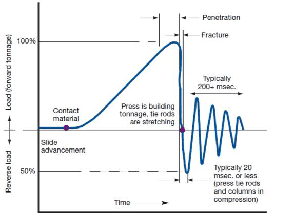
I think most of the stamping press shock is from snap-through, when the punch overcomes the material resistance and fractures the material.

snapthrough_jp4hv8.png
 
Hi all,

Thank you for your advise and input.

I haven't mentioned the intended use of the mechanism as I was looking for a parametric equation (which I have found).
In any case the mechanism is intended for providing linear motion (continues reciprocation of 100 cycles, each duty cycle) for a Foamer (frothing liquid to foam) for a medical device.
The foaming mechanism is rather small, about the size of a shoe box (with a ~650ml container).
Stats:
[ul]
[li]~240rpm (or ~4Hz)[/li]
[li]100 cycles[/li]
[li]~80mm stroke in one way (160mm for a full cycle)[/li]
[li]~1.5kg of reciprocating mass (in the worst case, might be a low as 0.8kg)[/li]
[/ul]

As this mechanism is intended for a medical device, I wanted to figure out if and/or how i need to dampen the (potential) vibrations of the mechanisms as the whole medical device is intended to be a table top device situated near the patient, so vibrations (and subsequent noise) is very undesirable.

For now, I'm considering using rubber dampeners for mounting the foaming assembly inside the medical device and mounting dampeners for the driving motor of the crank wheel.
Another change from the silider-crank mechanism is using a Skotch Yoke instead.
 
4-Hz airborne sound is not in audible range, with very few exceptions. Very soft vibration mounts would be needed, because the isolation frequency is very low and the table structure is typically not very rigid.

I would address the motor noise first and followed by noise flow from a nozzle. What type of motor and shaft speed? 2x line frequency electrical noise and noise from any speed reduction device (gears or belt) should be considered. Be careful with a Scotch Yoke, since the slider can wear and then create sound and vibrations from looseness.

Walt
 
1.5 lbs and a 3.15" ( or is it a 6.3"?) stroke.

Isolation mounts are going to be very soft because of the low frequency.

In addition they'll need to be even softer and bigger to accommodate the inch (25 mm) or so motion of the CG without transmitting force into the box and hence into the card table.
For 95% isolation mountings "Damping" will likely just INCREASE the transmissiblility of vibration across the mounting interface and into the patient's bedside table.
The various electrical and foam fittings are not going to enjoy tracking the wildly oscillating assembly either.

I think you need to make it a "Boxer" with an opposed slider crank assembly.
 
Way back when, I recall reading of this being an issue with steam locomotives. Specifically, they could counterbalance the wheels trying to eliminate the fore/aft vibration from the pistons & connecting rods, etc. (which translated into the locomotive swaying side to side), but then in doing so, wind up with vertical vibrations, which supposedly caused increased track wear and in severe cases could result in a wheel hopping at speed.
 
Status
Not open for further replies.
Back
Top