Eng-Tips is the largest engineering community on the Internet

Intelligent Work Forums for Engineering Professionals

Balancing a Vertical Pump Motor on a rubber base 6

Status
Not open for further replies.

RM12

Mechanical
Jan 29, 2024
29
0
0
US
I have been working on trim balancing a motor (Vertical pump motor) that was reconditioned. I was wondering if anyone has approached balancing vertical motors placed on a rubber pads (1/2 inch thick) to simulate a pump head attached in the field. Of course, the motor is clamped down on an isolation bed but with rubber pads between it. It is not clamped too tight which otherwise would be the same as placing it on the isolating bed without it.
Are there any existing papers or experiments done by others on this?
Thank you
 
Replies continue below

Recommended for you

Motor only, no pump ?

Are the bearings in the motor designed to operate with a partial vertical load ?

NEMA MG-1 defines acceptable mounting conditions for vibration testing. Section 9.5 in my 2009 edition.
- Rigid.
- Resilient

I fear the mounting condition you describe does not meet either requirement.
 
No pump. Only Motor.

It is not loaded whatsoever. The rubber pads are kept under the mounting base and then clamped to the isolating bed.

Yes, it does not meet the mounting conditions set by NEMA. This is an approach to determine if it would help this particular scenario.
 
Roughly how stiff are the pads? how heavy is the motor? what is the running speed?

There's no problem, in principle, in balancing a motor that is on rubber pads. So long as the motor is somewhat decoupled from the baseplate the usual approach for 2 plane balancing on an unknown machine should work. Another approach which simplifies things a lot is to dangle the motor from a crane. Then you get nice clean signals in the horizontal plane.

There's also a thread on 2 plane balancing an engine in the engine&fuel engineering forum

Cheers

Greg Locock


New here? Try reading these, they might help FAQ731-376
 
9.5.1.1 Resilient mounting.
The natural frequency of the support system and motor under test shall be lower than 33 percent the frequency corresponding to the lowest rotational frequency of the motor.​

Use this chart to get an idea of how squishy an isolation mount must be for a system resonant frequency less than .33X the motor rotational frequency.


A nice practical description of vibration isolation, including the perils of rotating equipment not mounted on grade, but on a mezzanine or 2nd floor.

General isolator design suggests the isolators should be up around the the same plane as the horizontal shaft equipment CG so the modes primarily will be translational, and not rocking, yawing etc modes at unexpected frequencies.
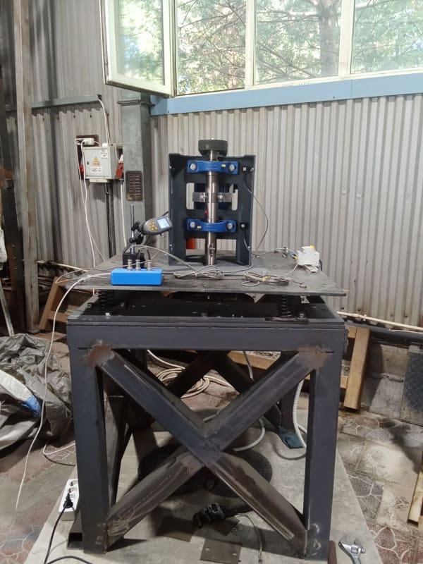
achieving that with your vertical shaft motor would likely require carefully engineered pedestals and a basket or scoop mount.

To evaluate your vertical motor's simplest unbalance vibration response I believe you'd want the motor to be able to translate horizontally on the mounts.

Real isolators are flexible in 3 directions.
Might use studs bonded to each side of a rubber biscuit.

If through bolts are used, there must be no metal-to-metal contact, and tightening the bolts must not overly compress the rubber.
Here is one method -

If a component directly bolted to a rubber pad the upward vertical stiffness is the very high stiffness of the bolt.
The vertical downward stiffness is that of the rubber pad. If the preload of the tightened bolt is sufficient, the there will be no vertical deflection until the applied force exceeds the preload.
 
The most important thing in the motor balancing process is to avoid a situation where the natural frequency of the system vibrations coincides with the motor rotation frequency. This phenomenon is called resonance, and it can lead to a significant increase in vibration amplitude.

In the context of an impeller motor installation, the use of vibration isolators, preferably spring isolators, is recommended to create conditions where the motor on the springs is slightly rocked. This allows the resonance to be shifted to low frequencies, well below the operating frequencies of the motor.

Here are examples of such stands, there is a video down there with a small engine. But the principle is also suitable for large engines, the principle is the same ..... or here for example :
1692890208122_dhthyk.jpg
 
I understand that and its very useful information.

I am still trying to figure out how would one know what the natural frequency of the entire system is?

Let us say I have a Vertical Motor that is going to be coupled to a pump. I dont have the pump.
I fix the motor and I need to balance it to bring the vibrations down. How can I simulate the same scenario of motor being coupled to pump when I don't know how the natural frequency of the system (motor +pump) changes?
 
Mount the motor "correctly" with a thoughtfully designed and tested, very flexible base, to essentially create a soft bearing balance machine.
Balance it.

1X Vibration amplification caused by resonance of a half-fast design of pump assembled to motor on a rule of thumb base plate shabbily grouted and anchored using leveling nuts to some random pump station floor to hopefully be dealt with then. The chances are about 50% the pump motor assembly was not rigorously designed, so the manufacturer //should// be invited to the show.
"Extra close" motor balancing tolerances are not likely to thwart that problem.
 
mojo97 said:
I am still trying to figure out how would one know what the natural frequency of the entire system is?

The resonant (natural) frequency of the system depends generally on the mass, frame stiffness and damping.

There are two simple experimental ways to determine the resonance.
1. Spin the rotor to the maximum frequency, turn off the rotor rotation and observe the vibration level until the rotor comes to a complete stop. By plotting the vibration you can see a sharp increase in vibration, which will be the frequency of resonance.
Bs1ManualEngV156-May2023-10418068.png

This is how it is shown on this image, for example. The resonance is at 700 rpm. You need a sensitive palm and a laser tachometer to determine the resonant frequency :)

2. Shock method. For that you will need any vibration analyzer. Here is an example:
Go to the spectrum graphs .Press the button to start measurements and hit the structure with a heavy mallet or sledgehammer preferably through a wooden spacer.
The analyzer makes a measurement and also displays resonant frequencies on the graph.

SpectrVibr_nvvzg9.png

This is how it is shown on this image, for example. The resonance is at 100 hertz, which is equal to 6000 revolutions per minute.
 
Tmoose

I couldn't really understand the second statement " 1X vibration amplification...."

Vibromera:

I am a novice in vibrations. I am not following on how 700 rpm is equal to 6000 revolutions per min?

Also do you mean maximum rotational frequency as - (60 HZ, for 2 pole 3600 rpm)?
 
1X vibration amplification refers to the increase in vibration amplitude occurring at the fundamental (or 1X) speed of the machine. This frequency is equal to the rotor or shaft speed. Vibrations at this frequency are the most typical and are usually associated with rotor unbalance.

In simple words 1x is the vibration at the rotor speed. It makes one oscillation per revolution.


700 rpm is equal to 6000 revolutions
I apologize, I corrected the message. It was a typo due to copypaste.

1 hertz contains 1 revolution per second.
If converted to minutes, 1 hertz = 60 revolutions per minute (60 seconds).

In the bottom screenshot the rotation speed is shown in hertz , in the top screenshot the rotation speed is RPM
 
Vibromera

Could you please explain why do you balance it on a flexible base?

I want to see if my approach are for the same reasons.
 
Balancing at the resonance frequency is generally impossible (with rare exceptions), and anything can resonate: the fan itself, some cover, or the table it is all mounted on. And finding exactly what resonates can take quite a bit of time. Using spring vibration isolators allows you to detune from various resonance frequencies. Generally, when balancing lightweight rotors, this is much easier than rigidly fixing it to the foundation.

Let me give you an example: one of our clients tried to balance a fan by welding it to a mounting table. The steel table was very massive, especially compared to the small fan. I don't remember exactly what the problem was, whether the table had a resonance at the fan's rotation frequency, or if it was standing on an uneven floor... In the end, until the client secured the table to the foundation with anchors, he was unable to balance it. It would have been simpler to place it on a soft base. For instance, here I just used a piece of thick foam to balance the fan:
I apologize , my English is not very good :) I hope I have written clearly )
 
I never fully understood the reasons why balancing at resonance would be problematic. IF the system is linear and stable then balancing at/near resonance should still work. But no doubt there can be problems in the real world.

I guess one possible problem is if high vibration vibration magnitudes push the system beyond where it acts linearly.

Another possible problem that comes to my mind is lack of phase repeatability near resonance. We can see examining the transfer function of a SDOF system that the rate of change of phase with respect to frequency is highest at resonance. This means that small changes in speed would cause changes in angle which would screw up the calculation. But more importantly, a small change in stiffness (maybe due to change in temperature or something loosening slightly between runs) would shift the resonance frequency and shift the curve which would again cause a large change in angle for the same speed since we remain in the part of the curve near resonance where rate of change of angle with respect to frequency is large. In contrast a small change in stiffness or resonant frequency doesn't cause as much change in angle when initially far above or far below resonance where the phase vs frequency curve is a lot flatter.
 
I completely agree with balancing it below resonance.

My question is when we add a spring or a rubber base to detune it from the resonance frequency of the electric motor and balance it.
How does that ensure that the electric motor when installed in the field won't change to a different resonance frequency and coincides with the changed resonance frequency we ran it at?
 
MOjo97 said:
I was wondering if anyone has approached balancing vertical motors placed on a rubber pads (1/2 inch thick) to simulate a pump head attached in the field
I don't think that is going to do a good job of simulating field conditions. But it is suitable for test run and for balancing. It is generally not necessary to simulate field conditions for test run. NEMA and EASA don't require matching field mounting conditions for testing new or refurbished motors, they only tell you to make sure you're not testing on a test stand whose natural frequency is near running speed (i.e. make sure the test stand meets requirements for either resilient or rigid mount).

MOjo97 said:
My question is when we add a spring or a rubber base to detune it from the resonance frequency of the electric motor and balance it.
How does that ensure that the electric motor when installed in the field won't change to a different resonance frequency and coincides with the changed resonance frequency we ran it at?

Shop testing does nothing to make sure the motor won't be resonant (installed natural frequency near running speed) after installed. And the he natural frequency which existed on the test stand is not relevant to whether the motor will be resonant when installed or not.

So let's back up and separate it into two questions which are distinct from each other and which have distinct answers:
[ol 1]
[li]How to make sure the natural frequency when mounted on test stand is below running speed during shop test / balance. Put rubber under, bump test if you want. In theory you can measure static deflection and use that to compute a resonant frequecy. [/li]
[li]How to make sure natural frequency when mounted on the pump is not too close to running speed during operation. Check the history of what was going on with the motor before refurbishment because refurbishment will not likely change the resonant frequency (as long as it was bolted tight to the pump before/after). Otherwise, you could just install the motor and then bump test it (or run it). Or if you have identical sister units, bump test them. If you want to try to estimate it before installation without any comparison to past/sister installations, then you're probably going to have to do calculations (which often have a lot of uncertainty). [/li]
[/ol]
 
THANK YOU!

That makes complete sense now. I wanted to follow up on this:

1- The only reason a rubber pad or a flexible base is used is, if the resonant frequency is too close to the running frequency. My question is why then the phase angle changes for vibrations in comparison to with & without rubber pads.
2- Would you have any links or resources to study calculating resonance frequency from the static deflection of the rubber pads.
3- " then you're probably going to have to do calculations "- what would I need to calculate and also any references that I can study with or start.
 
1- The only reason a rubber pad or a flexible base is used is, if the resonant frequency is too close to the running frequency. My question is why then the phase angle changes for vibrations in comparison to with & without rubber pads.
Let's say we use the rotor keyway as a phase reference. Assume unbalance force is driving the vibration.
That unbalance force force has a constant phase no matter how you change the speed or resonant frequency.
But to compute the response, we multiply the vector force times the vector transfer function. That means we add the angles. I previously linked a graphic which included magnitude and angle for the transfer function from force to displacement. If we define the force angle as zero then the displacement response angle is the same as shown on that transfer function. You can see that it would vary depending on where natural frequency is in relation to running frequency. Rubber pad shifts the natural frequency which shifts the displacement phase for a given forcing function.


2- Would you have any links or resources to study calculating resonance frequency from the static deflection of the rubber pads.
If you can measure the static deflection of the rubber (what distance does it compress when you put the weight on it), then assuming it acts like a linear spring and assuming the system acts like a SDOF (pure vertical motion, no rocking), we can analyse as follows:

F = k*SD = mg  (spring force supports weight)
solve SD
SD = m*g/k = g*(m/k)
subs m/k = 1/w_nat^2
SD = g / w_nat^2
solve w_nat
wnat = sqrt(g / SD)
fnat = 2*pi*sqrt(g / SD)
fnat = 187.7/sqrt(SD) where fnat in cpm and sd in inches

3- " then you're probably going to have to do calculations "- what would I need to calculate and also any references that I can study with or start.
Hmmm that's a tall order. It's a broad subject and the starting point is not clear. I don't have anything handy to post at the moment but I'll think about it. Maybe someone else has some good links handy.

In most cases, a bump test is a more direct and reliable approach than calculations mentioned in questions 2 and 3.
 
" 2- Would you have any links or resources to study calculating resonance frequency from the static deflection of the rubber pads. "


Use this chart to get an idea of how squishy an isolation mount must be for a system resonant frequency less than .33X the motor rotational frequency.
The left hand Y axis relates static deflection (inches) to resonant frequency ( cpm/rpm)

A nice practical description of vibration isolation, including the perils of rotating equipment not mounted on grade, but on a mezzanine or 2nd floor.

NEMA MG 1 Section 7 discusses this some. Attached image has a chat similar to the Mason chart above.
primarily for motors with shaft horizontal.
Your vertical motor adds complications of isolator lateral stiffness. And the foot print of the motor face vs mount location most likely introducing some pesky rocking resonant vibration modes.

Have you mentioned the equipment you will use for balancing ?
 
Status
Not open for further replies.
Back
Top