Continue to Site

Eng-Tips is the largest engineering community on the Internet

Intelligent Work Forums for Engineering Professionals

  • Congratulations MintJulep on being selected by the Eng-Tips community for having the most helpful posts in the forums last week. Way to Go!

Ball and Screw Inerter

Status
Not open for further replies.

karthik261262

Mechanical
Feb 6, 2017
6
Hello everyone,

I am trying to manufacture a Ball and Screw Inerter for my research.
can some one help me on how to attach the ball nut to thrust bearing.
So that it should not move, when the screw rotates.

Thanks in Advance
 
Replies continue below

Recommended for you

What the hell is an 'inerter' ?


Mike Halloran
Pembroke Pines, FL, USA
 
It's an inertia like force element with two attachments, that is, it exerts a force proportional to the difference in acceleration of the two ends. They are used in motorsports.

Cheers

Greg Locock


New here? Try reading these, they might help FAQ731-376
 
Well, I'll be dipped in ... er, used food. Again.

Thanks, Greg.


Mike Halloran
Pembroke Pines, FL, USA
 
Okay, Karthik, with my newfound knowledge I can conjecture what an inerter built around a ballscrew might look like:

It might comprise a ballscrew assembly with the ball nut attached firmly to a heavy mass, which is free to rotate inside a shell, and free to rotate relative to the shell, thanks to a sturdy thrust bearing which transfers axial loads to a bulkhead within the shell.

The shell and one end of the ballscrew are coupled to two objects that move relative to each other, so that the ballscrew translates in and out of the shell, just like the rod of a shock absorber, and the ball screw is prevented from rotating by its attachment to the external mechanism, and the shell is similarly coupled to the external structure and prevented from rotating.

I.e., the ballscrew is used in reverse from the the usual situation, where instead of the nut rotating and driving the screw, the screw translates linearly and drives the nut in rotation.


... but you seem to be talking about a different arrangement, where the screw rotates as part of its primary function.
Do you have a drawing of the mechanism about which you are speaking?


Mike Halloran
Pembroke Pines, FL, USA
 
Hi Mike,

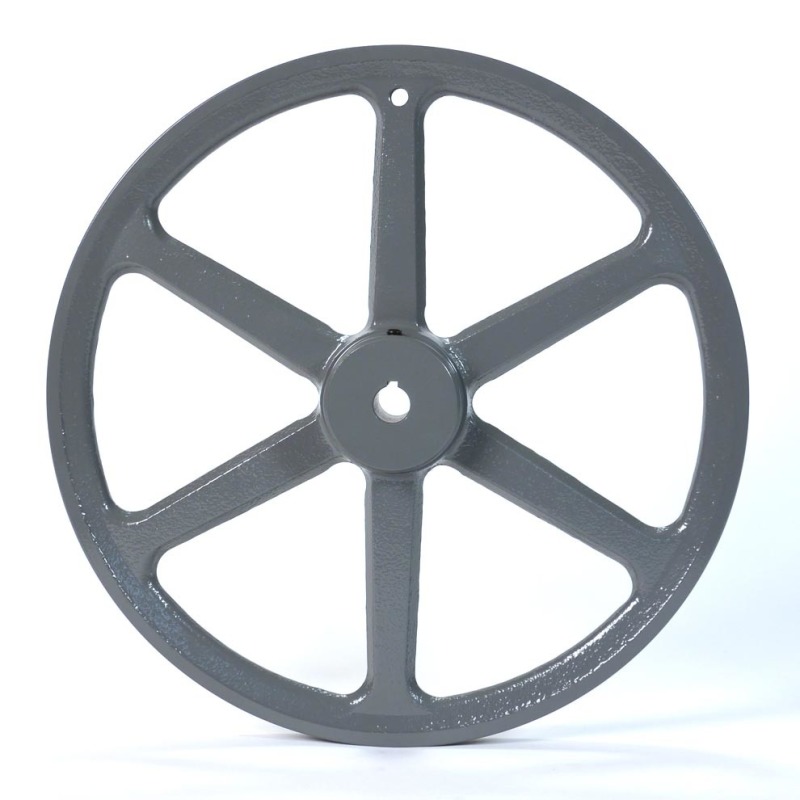
I will attach the ball but to a fly wheel.

So when nut rotates, fly wheel will also rotate.

ball screw can be used in two types

1) when screws rotates, nut will have linear motion
2) when screw translates, nut will rotate.

I thought of using the second one here,

The problem is how will i attach the Nut to a Fly-Wheel.

Flywheel__00115.1363382457.1280.1280_sgnaqz.jpg
- Fly wheel

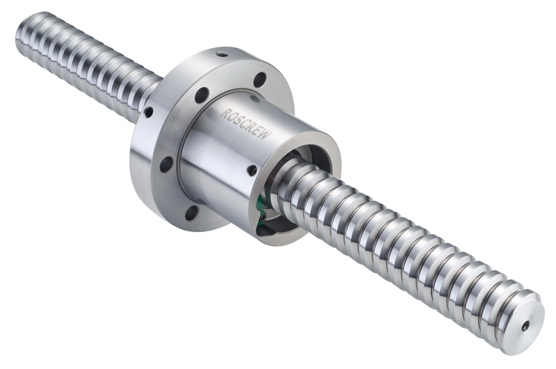
roller_screw_ballscrew_large_uwqfih.jpg
- Ball screw Mechanism

How to fasten these both, please help me.

This is not my drawing, these are used to visualize.

Thanks,
Karthik.
 
Rather than trying to adapt a spoked pulley, go to your steel service center, and have them flame cut a disc from ~2" plate, bore a central hole to fit the ballnut shank, and drill and tap a pattern of holes to fit the ballnut flange.

I don't think it's going to work in quite the way you are imagining it, unless I have misunderstood your intent.


Mike Halloran
Pembroke Pines, FL, USA
 
Mike,

I am manufacturing a miniature one.

It will be about 3-4 inches in length and 1-1.5in in diamater.

I though of 3D printing a fly wheel and i will attach the nut to the hub.

The problem is the nut is of very less thickness.

So how would i attach that to fly wheel hub?
 
I hope you are buying a commercial ballscrew assembly.
The nut will probably have some kind of flange with multiple through holes for bolts.
Make your flywheel from a piece of steel plate.
Actually, for 1.5" diameter, it could be sliced from a ~2" steel bar by any competent machine shop, in less time and for less money than a 3D printed anything will cost you.

This would probably be a good time to start work on a proper assembly drawing of what you propose to build. That should help us both understand what the other is talking about, and allow my friends here to also comment.


Mike Halloran
Pembroke Pines, FL, USA
 
MIKE,
Even i thought the same.

I will try to attach the fly wheel to the flange of the nut using bolts.

No worries of 3D printing, as my lab has 2 3D printers.

IRstuff - only then it would be an inerter, i will try to make it work.
 
IRStuff said:
Your 2) won't work because friction is too high and mechanical leverage is too low.

A ball screw sized such that back drive torque is higher than friction torque will behave as described (will impart rotation in the nut when the shaft is translated if the nut is free to rotate) with varying levels of efficiency depending on the Tbc and Tf ratio.
 
Status
Not open for further replies.

Part and Inventory Search

Sponsor