Continue to Site

Eng-Tips is the largest engineering community on the Internet

Intelligent Work Forums for Engineering Professionals

  • Congratulations KootK on being selected by the Eng-Tips community for having the most helpful posts in the forums last week. Way to Go!

Barrier for building

Status
Not open for further replies.

DQD

Structural
Feb 15, 2021
3
I have to design some vehicle barrier for the proposed building. Load given is 800-1000 kN applying at around 2m from NGL.
I was asked to use the external structural wall/column to resist but I am not comfortable with that. Instead, I am thinking about having extra cantilever barrier (shown in red at LHS) from slab/capping beam to hold the load. Do you think it is doable? what about the connection and the effect to PT slab?
I also have this scenario where there is no slab for me to cantilever. So I am thinking having RC post (shown in red at RHS) embed into soil.
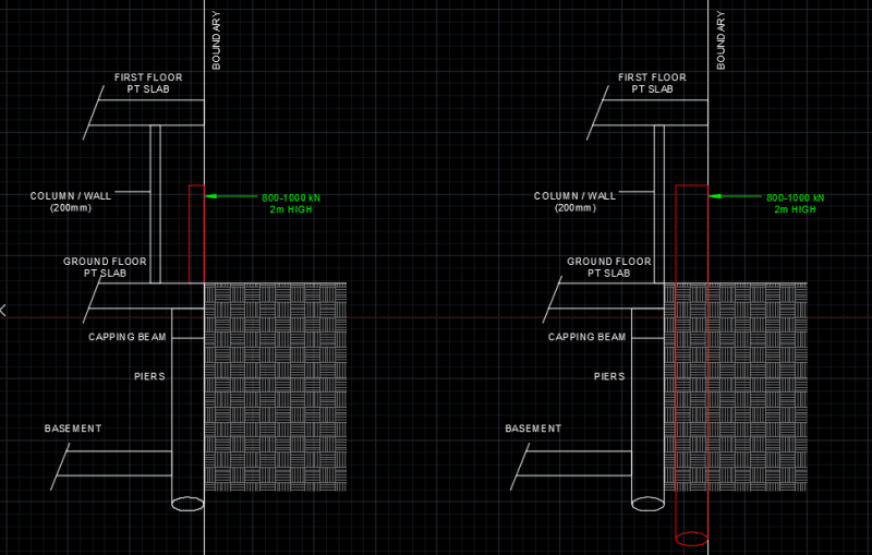
56666_mpvfo2.png


What is your thoughts?
Thank you.
 
Replies continue below

Recommended for you

80 to 100 tonnes at 2 m?? Thats a long way up for a vehicle barrier.

There are lots of posts here on vehicle barrier design and most use a form of energy absorption. A force at a distance works, but only to a certain extent as what is your criteria for movement of the post?

This little snapshot of the design tells us very little about what the actual impact direction is, why it is so close to the boundary or what it is exactly you're trying to stop hitting what.

Remember - More details = better answers
Also: If you get a response it's polite to respond to it.
 
Thank you for your help. For either cantilever wall as shown on the LHS or the cantilever post shown on the RHS, as long as the main structure is not damaged, the movement for these cantilever component doesn't really matter. I have about 1000mm gap from boundary to the external walls. The building is close to the boundary but the traffic is about 3meters away from boundary. I was given the load instead of speed (It is a tram).
Not sure how energy absorption is performed. I believe it should be something like this? External energy: 0.5*mv^2. And then the internal energy is the sum of resultant stress times the strain (forces times displacement). Do you have any design example that you recommend?
I try to use the force 800kN times the height to work out the moment at cantilever end and design the RC member. Looks like 450mm thick cantilever wall works. Anything that I miss?
Thank you.
 
Trams run on rails. Why is it hitting a building?

Do a search here for vehicle barriers. There are many DOT specifications and designs to help you and lots of posts.

A load without an allowable deflection means nothing.

Remember - More details = better answers
Also: If you get a response it's polite to respond to it.
 
Yeah and thats why I didnt take into consideration at the beginning and now I am asked to do so by the authority. Maybe it is to consider the accident like the derailment?
I tried to search a bit but no luck so far.
Much appreciated if anyone has any design examples to share whether it is based on force or energy.
 
They've given you a force, so design for that. A design force is common for derailment. The energy absorption will come from redirecting the tram so it can just run to a halt, crushing of the tram, and damage to the structure. Not an exact science obviously so just run with the load that has been specified.

A separate protection structure is a good thing. You might also consider general robustness of the building in case the tram still hits that wall.
You don't want the building falling and injuring its occupants, or causing even more injury to the train passengers.
 
DQD:
Keep in mind that when your barrier posts are loaded by an impact, they will impart a surcharge loading on the bldg. foundation, when they are that close to the bldg. Any energy approach just has too many variables which you can’t pin down, without much testing. I would use the load you were given, and apply it at 2m if that’s what they want. But, add three horiz. rails, one at 2m ht. on the outside of your barrier post. You want the impact loading to be distributed to three, four or five post, not just one post. Three or five posts implies that the middle post is the impact location, four posts implies that the impact is btwn. two posts. The relative stiffness of the posts and the rails comes into play here. Pay some attention to bumper heights on cars and trucks (typical traffic) and the floor framing system ht. and coupler/draft gear ht. on the railcars, the stiffest locations on that equip., as you locate the other two rails, the rest is kinda crumple zone on all the traffic equip. You might take a look at loading dock bumpers, etc. or even marine docking shock absorbing equipment for some inspiration. You do want to absorb and dissipate some impact energy, rather that shoot it all into the posts and bldg. found. if you can. That’s the advantage of cable systems along highways; the cable stretches, bends a bunch of posts and limits the stopping distance during an impact, slows it down, absorbs a bunch of enery.
 
Your energy absorption will be primarily elastic, then go plastic as failure occurs. You will need force-distance curves for each resisting element (difficult to derive) and will then have to find the reactions for the combined elastic/plastic system.
 
Status
Not open for further replies.

Part and Inventory Search

Sponsor