Continue to Site

Eng-Tips is the largest engineering community on the Internet

Intelligent Work Forums for Engineering Professionals

  • Congratulations waross on being selected by the Eng-Tips community for having the most helpful posts in the forums last week. Way to Go!

Base Plate Design

Status
Not open for further replies.

dherna45

Structural
Mar 6, 2017
19
Hello, My name is Daniel.
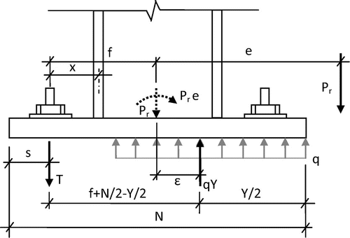
I am designing a base plate connected to a pad foundation with a grade beam on top of the pad footing. I have a axial load and moment transfering to the foundation. I found a page that says that when moments act at a foundation, it is normal to replace them by a vertical load and an equivalent eccentricity. I would like to know the reason behind this. Thank you very much for your help
 
Replies continue below

Recommended for you

Well each moment M can be replaced by force F and an eccentricity e
M = F x e


best regards
Klaus
 
I'm not sure of the real reason, other than it gives a location for the placement of any foundations... Should be centered on the eccentric location.

Dik
 
one reason might be...
if the (resulting) force is acting within the core section....the foundation will not turn over and there is no gap
between foundation and ground
therefor an existing moment can be transferred to force to see if this force is within this core area


best regards
Klaus
 
I understand that a point load with a eccentricity is equal to a moment. But on the picture, The point load with the eccentricity is being equal to a moment and also an axial load at the moment's location.
Shouldnt It just be equal to the moment?

figure3_mojmvf.gif


Thanks for your help.
 
The moment is CAUSED by the vertical load, that does not mean that the vertical load goes away
 
Well, to start off, your resultant uniform pressure diagram to the bearing plate is wrong.

It is more triangular in nature with the resultant at the kern of the triangular pressure prism, giving a greater eccentricity.

There is a good diagram and example in Blodgett's "Design of Welded Structures" on how to analyze the problem on pages 3.3-8 through 3.3-10.

I suggest you look there to start.

There are more complex models, but the equations listed do give a solution.

Mike McCann, PE, SE (WA)


Mike... I usually use a rectangular stress block like I do for reinforced concrete...

Dik
 
Mike, the diagram is from AISC's Design Guide 1.

Since the column is embedded in a grade beam, I might design the grade beam and column to grade beam connection to take the moment (unless is a tie beam rather than a grade beam designed for bending).
 
Well, if this is accepted practice now, then it is less conservative than 50 years or so ago when Blodget did his sketch, ultimately yielding a thinner base plate.

Mike McCann, PE, SE (WA)


Status
Not open for further replies.

Part and Inventory Search

Sponsor