Eng-Tips is the largest engineering community on the Internet

Intelligent Work Forums for Engineering Professionals

  • Congratulations waross on being selected by the Tek-Tips community for having the most helpful posts in the forums last week. Way to Go!

Baseplate bending line for thickness determination 5

Status
Not open for further replies.

steel_plate_arch

Civil/Environmental
Jun 19, 2020
4
0
0
US
Hello,

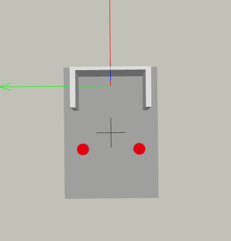
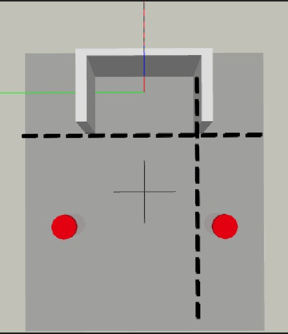
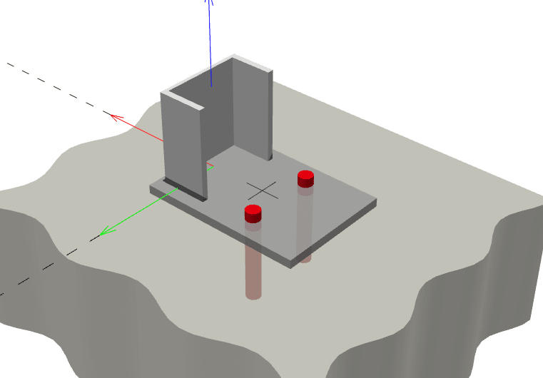
How exactly do I calculate the effective bending line on a base plate like shown below?
I've read that there are 45 degree projection lines that comes from the bolts. What about the farther bolt from the bend line? Is that one also projecting and therefore causes a larger line?

Visually I am having trouble determining how this bending line comes out to be. I've seen in another eng-tips post that also mentions including the perpendicular distance as well, so not sure about that one.

Hope someone can point me in right direction.Thanks.
Capture2_mxgech.png

Capture1_v2cuhy.png

Capture4_nojlap.png
 
Replies continue below

Recommended for you

I don't believe the bolt layout was wisely chosen. If this is still in the design stage, it would seem reasonable to increase the number of anchor bolts and adjust their location to something a little more sensible.
 
Thanks bones - I've yet to bite the bullet and buy Profis Premium, though it does seem well worth the value.

In this case, it seems the flexural restraint at the channel is not being accounted for and the plate is completely free to rotate about the bolt line, thus we're only seeing the one hinge. Not sure Profis could capture this restraint anyhow.
 
No, Profis could not without knowing the EI and length of the channel. That was not given and neither was dimension 'a' nor the width of the plate.
 
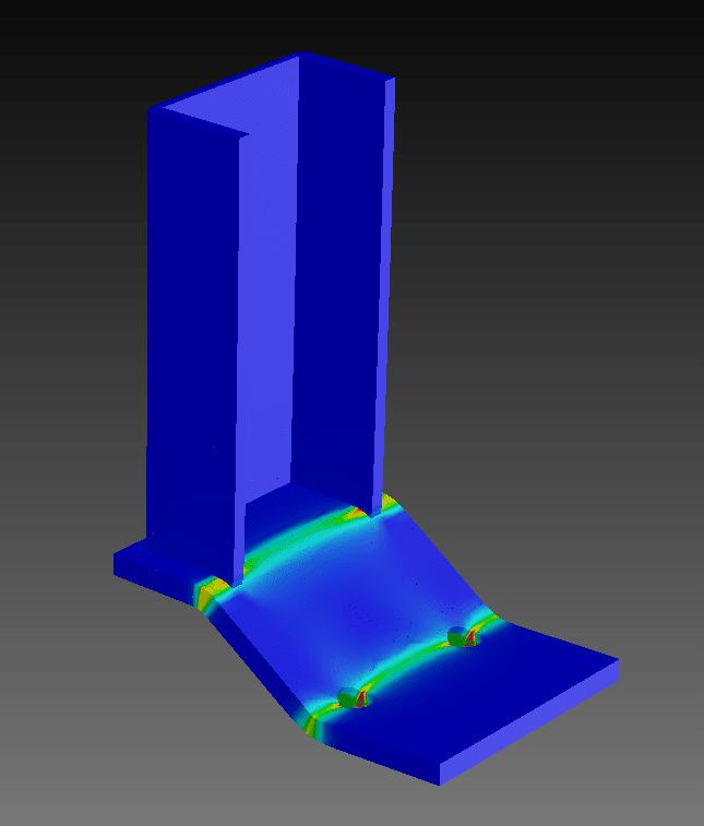
I just did a mockup with arbitrary sizes and materials for proof-of-concept demo purposes. What I think it's showing is initial yield line forming at the bolts, then progressive spread of plasticity in the base plate in the direction of the channel. I visualize this deforming in a curled shape similar to the prying action figure that Flotsam posted. It's too bad Profis does not provide a deformed shape in it's output.
 
I was curious what this would look like, so here is my quick and dirty FE model. This is showing the plate curvature, so it gives a nice idea of where the yield lines are forming. Nothing unexpected.

Capture_nxwlqj.png
 
If it were me I'd still limit the plate to first yield and avoid prying in the anchors unless the results were unreasonable. This will also help limit deflection.

Anyhow, I think we've lost the OP's interest at this point [bigsmile].
 
plus significant prying action...

-----*****-----
So strange to see the singularity approaching while the entire planet is rapidly turning into a hellscape. -John Coates

-Dik
 
I would not argue with Flotsam7018 on limiting the plate to first yield. One additional anchor bolt at the c.g of channel would seem like a good idea too.
 
@bkal...

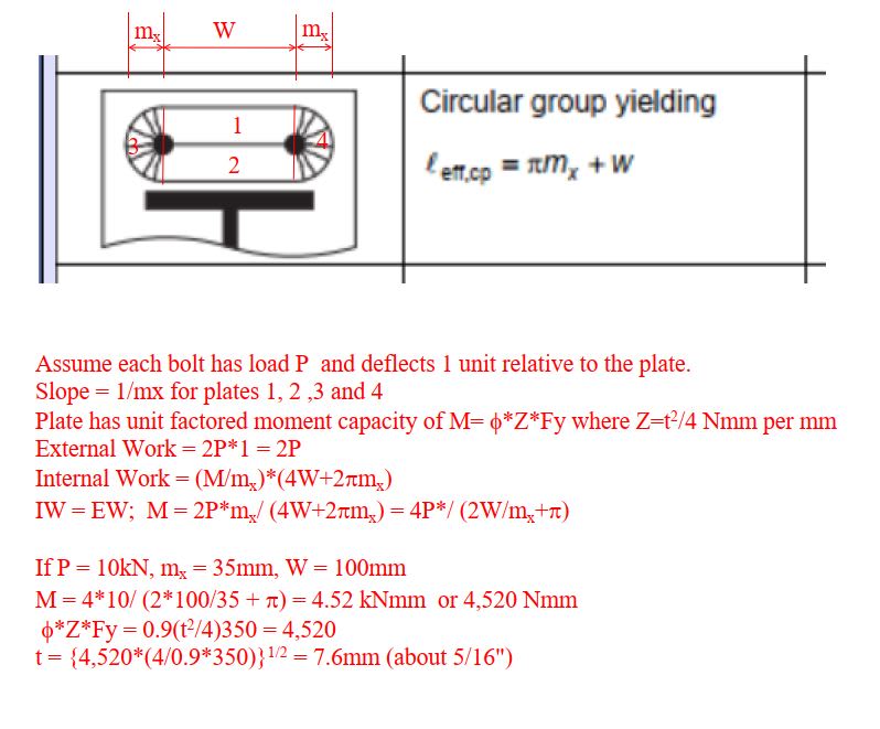
is there more to that image? and what does the l[sub]eff[/sub] mean? This is useful information to have. What is the source? Thanks...

-----*****-----
So strange to see the singularity approaching while the entire planet is rapidly turning into a hellscape. -John Coates

-Dik
 
dik - the l[sub]eff[/sub] is just the effective bending width.

This AISC white paper by Bo Dowswell is a favorite of mine if you haven't come across it previously:
It goes over many different yield line solutions presented throughout the years (including some of those in bkal's reference) providing experimental results and comparison, rules of thumb for when certain yield lines would control, etc. A truly great reference.
 
Thanks... downloaded both articles. The l[sub]eff[/sub] is used to determine the plastic section modulus using l[sub]eff[/sub]*t^2/4? I'll take a look at the articles; I wasn't aware of them... again, thanks...

-----*****-----
So strange to see the singularity approaching while the entire planet is rapidly turning into a hellscape. -John Coates

-Dik
 
Thanks BART... just confirming... value times Zx (Sx down under) gives the moment resistance. I haven't had a chance to look at the publication that shows that l[sub]eff[/sub] really is.

-----*****-----
So strange to see the singularity approaching while the entire planet is rapidly turning into a hellscape. -John Coates

-Dik
 
dik said:
value times Zx (Sx down under) gives the moment resistance

In some cases, that is true but consider the third example of Circular Patterns. The value given for l[sub]eff[/sub] must be considered carefully. The value listed can't be used directly for all yield line patterns.

Capture_jcjstq.jpg
 
again, thanks...

-----*****-----
So strange to see the singularity approaching while the entire planet is rapidly turning into a hellscape. -John Coates

-Dik
 
Status
Not open for further replies.
Back
Top