Hi,
I am new to GD&T and learning from mainly Youtube videos (a couple of references I found from this site including Mr. R Dean Odell's excellent playlist). I am yet to invest in a good GD&T book (I keep on hearing Bruce A Wilson as an excellent one but $100 is not something I can afford currently). Anyways, I have a question which is rudimentary in nature but I feel like it is a very important concept I need to grasp.
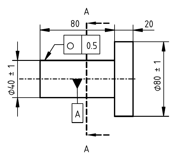
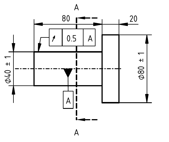
Lets consider part shown below. I have made two versions of feature callouts. The drawing was made using FreeCAD and I am yet to get a good grasp on its workings. I hope I haven't screwed up the GD&T symbology in the drawings...
NOTE: I have intentionally omitted tolerances to horizontal dimensions in the drawings.

Drawing #1

Drawing #2
What I want to know is that if an inspector is doing measurements for the part (lets say at Section A-A) using both versions of drawings, how does Datum A come in to play wrt Runout? I hope I am articulating my understanding properly here...In the first Drawing, an inspector would check at Section A-A for variation in basic dimension (Dia 39 to 41) and then check for circularity using a dial gauge...they would do a similar procedure when working with Drawing 2, correct? What role does Datum A play in outcome in Drawing 2?
I forgot to mention in Drawing but all dimensions in are millimetres.
Thanks,
-B
I am new to GD&T and learning from mainly Youtube videos (a couple of references I found from this site including Mr. R Dean Odell's excellent playlist). I am yet to invest in a good GD&T book (I keep on hearing Bruce A Wilson as an excellent one but $100 is not something I can afford currently). Anyways, I have a question which is rudimentary in nature but I feel like it is a very important concept I need to grasp.
Lets consider part shown below. I have made two versions of feature callouts. The drawing was made using FreeCAD and I am yet to get a good grasp on its workings. I hope I haven't screwed up the GD&T symbology in the drawings...
NOTE: I have intentionally omitted tolerances to horizontal dimensions in the drawings.

Drawing #1

Drawing #2
What I want to know is that if an inspector is doing measurements for the part (lets say at Section A-A) using both versions of drawings, how does Datum A come in to play wrt Runout? I hope I am articulating my understanding properly here...In the first Drawing, an inspector would check at Section A-A for variation in basic dimension (Dia 39 to 41) and then check for circularity using a dial gauge...they would do a similar procedure when working with Drawing 2, correct? What role does Datum A play in outcome in Drawing 2?
I forgot to mention in Drawing but all dimensions in are millimetres.
Thanks,
-B
