Continue to Site

Eng-Tips is the largest engineering community on the Internet

Intelligent Work Forums for Engineering Professionals

  • Congratulations KootK on being selected by the Eng-Tips community for having the most helpful posts in the forums last week. Way to Go!

Basic GD&T Concept Question

Status
Not open for further replies.

Burner2k

Aerospace
Jun 13, 2015
193
Hi,
I am new to GD&T and learning from mainly Youtube videos (a couple of references I found from this site including Mr. R Dean Odell's excellent playlist). I am yet to invest in a good GD&T book (I keep on hearing Bruce A Wilson as an excellent one but $100 is not something I can afford currently). Anyways, I have a question which is rudimentary in nature but I feel like it is a very important concept I need to grasp.

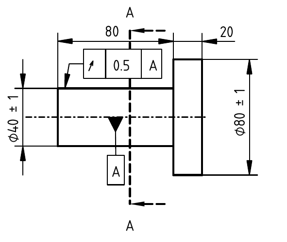
Lets consider part shown below. I have made two versions of feature callouts. The drawing was made using FreeCAD and I am yet to get a good grasp on its workings. I hope I haven't screwed up the GD&T symbology in the drawings...

NOTE: I have intentionally omitted tolerances to horizontal dimensions in the drawings.
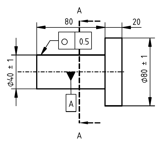
Circ_jsdo3p.png

Drawing #1

Runout_hp3qd4.png

Drawing #2

What I want to know is that if an inspector is doing measurements for the part (lets say at Section A-A) using both versions of drawings, how does Datum A come in to play wrt Runout? I hope I am articulating my understanding properly here...In the first Drawing, an inspector would check at Section A-A for variation in basic dimension (Dia 39 to 41) and then check for circularity using a dial gauge...they would do a similar procedure when working with Drawing 2, correct? What role does Datum A play in outcome in Drawing 2?

I forgot to mention in Drawing but all dimensions in are millimetres.

Thanks,
-B
 
Replies continue below

Recommended for you

Welcome to the world of GD&T! First of all, the datum feature symbol (triangle) shouldn't be attached to the axis. While the datum is in theory an axis, you should label the physical feature that the axis will be derived from (in your case, the larger diameter on the right). Look back on all your videos or other training materials and you'll see how that should be identified (well... the good videos should get it right).

But to your main question: Circularity by definition never relates to a datum; it just checks the form of that smaller diameter's surface unto itself. So, if checking that first drawing with a dial indicator, the inspector has to be very careful to rotate the part around the axis of that small diameter (doing that can be tricky, and could be a separate discussion).
In the second drawing, circular runout is more powerful: It is like taking the circularity idea but relating it to a datum. Thus, circular runout controls not only form, but also location and orientation of that smaller diameter with respect to datum axis A.

John-Paul Belanger
Certified Sr. GD&T Professional
Geometric Learning Systems
 
Hi, Burner2k:

Datum feature symbol A needs to be attached to feature(s) rather than an imaginary line.

Best regards,

Alex
 
Wilson's books are cheaply available on e-bay and Abe Books ($30-$40), depending on version) and Powell's Books (presently only new versions)

Go for the '2009 copyrights or later. Most of the concepts are the same and there are websites that cover the main differences.

Be aware there are two books with identical titles
"GD&T: Application and Interpretation by Bruce A. Wilson" for the latest version - the cheaper one is the Study Guide and has a small yellow block at the top edge.
 
Every time I have seen someone specify concentricity or circularity or cylindricity, they intended to measure runout.
 
I cannot wait for someone to realize that concentricity isn't the same control as position and it gets a comeback. The only reasons I see for its removal is that most users don't understand it or somehow use it wrong. I used to see poor datum feature selection all the time and no one is trying to remove those.

What I cannot understand is how circularity survives. If one is allowed to choose the plane to evaluate it then a nominally elliptical feature could be measured as perfectly circular. At least cylindricity is self-orienting.
 
Hello,
I am not that familiar in using FreeCAD software and could not figure out how to attach Datum symbol to larger diameter. Please excuse the error. I just wanted to convey which is Datum A in my drawings for question purpose only.

Belanger, thanks for your reply but I am still not clear on the role of Datum. Let me try to watch a few videos on runout and perhaps it will answer my question.

I am located outside North America and not sure with shipping expenses and all, how much an used copy of Bruce Wilson on Ebay would end up costing. But nevertheless, a good suggestion. I'll check it out!
 
Since you appear to be in India, buy the electronic version of Y14.5-2018 and skip approximations. It is too expensive, but over 10 years, it will average $2/month. Unless you intend to quit in fewer than 10 years.
 
Burner2k... Imagine if the two diameters were not aligned properly (not concentric/coaxial) by accident. In that case, the circularity tolerance could still pass because the shape of the part could still be perfectly round.
But the circular runout tolerance would probably fail because the small diameter is out of tolerance when measured against datum A. Circular runout looks to be centered around datum A, which circularity does not do.

John-Paul Belanger
Certified Sr. GD&T Professional
Geometric Learning Systems
 
3DDave - I don't believe one can freely choose the plane in which circularity is evaluated. The cutting plane in which circularity is evaluated is defined to be perpendicular to the (tangent-continuous) spine of the feature. The spine of the feature is the derived median line, obtained by taking cross sections of the UAME. If the derived median line is not tangent-continuous, it can be made tangent-continuous by filtering out surface defects that yield a discontinuity of the derived median line.
 
Jacob Cheverie,
I don't think the circularity cross sections must be taken perpendicularly to the DML. If I recall correctly, ASME Y14.5 mentions "axis or spine" without detailing further. The mathematical definition standard Y14.5.1M-94', again if I recall correctly, mentions "some spine".
You're welcome to check in these standards and confirm or refute.
I take that to mean that fitting (optimization) is allowed, and as long as you can find a spine that will provide the required circularity conformance when sections are taken normal to it - you're good.

With that said, I don't share 3DDave's viewpoint that circularity can always be forced into tolerance. There is only that much manipulation possible when all sampled cross sections must be normal to the same spine. I also don't see how one can find a cross section on a feature that was produced elliptical that will make that element appear circular. It can only be vice versa.
 
Too be fair I was being lazy - I see no reason for circularity to ever to applied. There is no zero width interface between parts. At best one should apply a cylindricity on a per-length basis, but I'm too tired of the arbitrary restrictions to look it up to see if ASME committee members made the effort to say that cannot be done.
 
3D Dave- I agree. I can see cylindricity maybe having a use to refine a primary datum feature, but I can't see many situations where circularity is really needed.

I'm sure some industries have special needs, and I know specialized equipment exists for the purpose of verifying circularity. My argument is that if you need some special machine to check the characteristic, then it could be done specified in some other way than having a symbol in the standard.
 
Cylindricity may not always be a suitable replacement for circularity. What if someone wants to refine the form of a cone in a way that is not restrictive to the included angle, unlike what a tight profile tolerance would do?
 
Hi All,

I agree with Burunduk that the cross sections for Circularity need to be perpendicular to a spine, and that the spine can be an arbitrary curve. The axis of the UAME and the DML are usually good candidates for the spine, but not always. I believe that Y14.5 included the arbitrary spine in the definition in order to allow Circularity to be applied to cylinders (or cones) with a large amount of as-produced curvature/bending. Tubes or hoses for fluid flow, for example.

I would also agree that there are applications in which Circularity is needed and Cylindricity would not suffice (such as the bendy tubes described above). But these applications are few and far between, and we could question whether or not Circularity deserves to have its own symbol in the standard.

Evan Janeshewski

Axymetrix Quality Engineering Inc.
 
Status
Not open for further replies.

Part and Inventory Search

Sponsor