Continue to Site

Eng-Tips is the largest engineering community on the Internet

Intelligent Work Forums for Engineering Professionals

  • Congratulations GregLocock on being selected by the Eng-Tips community for having the most helpful posts in the forums last week. Way to Go!

basic question about coefficient Ka 2

Status
Not open for further replies.

killswitchengage

Geotechnical
Jan 5, 2015
363
Hello
i need help fast , if you substitute a certain amount of back fill behind a retaining wall with gravel for drainage . What will be the coefficient of earth pressure Ka to take ? will it be the Ka of the gravel or that of the true backfill behind (for ex clay) ?
 
Replies continue below

Recommended for you

If it was just a 200mm wide gravel trench immediately behind the wall with a perforated drain at the bottom i would use the Ka for Clay. However if it was a substantial width then it might be worth considering.

What soil paramters are you using for clay and gravel?

Assuming friction angle of 32 for gravel and 24 for clay then using Ka for Clay would be more conservative.

A sketch with soil parameters would help a lot.
 
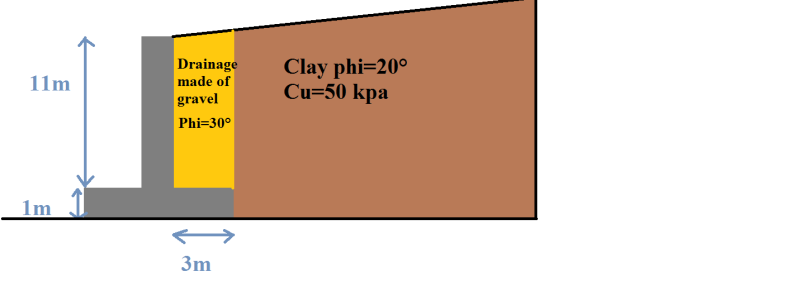
well to make it simple the drainage backfill against the wall is about ( 3.00m*12 m) made out of gravel maybe 35° friction angle , behind it there is a fill we believe it have angle of friction about 20° so which Ka to apply in this case
 
Explain the 3 x 12 dimension. Is all this in one plane and which is horizontal and which vertical.
 
Appears that you know already how much far from the wall you will be backfilling with gravel. How height is the wall? If the gravel covers the entire active wedge zone I would use the gravel's phi to calculate ka. If you don't have too much gravel so the clay is within the active wedge zone, then I would use the clay to calculate ka.
 
Agree with Okiryu...sounds like Ka for gravel would be more appropriate, assuming 3m wide backfill, 12m deep.

If the reverse of that (12m wide by 3m deep), then no question it is gravel Ka.

The active pressure from the clay will be attenuated in the gravel, but the gravel still has a reasonable component.
 
A description of the wall type (mass gravity, cantilever, MSE...) and how the measurements are defined would help, sketch? For example, a cantilever concrete wall typically has two measurement points, directly behind the stem and then behind the footing so knowing where you are measuring from is important.

A general rule is if you go a short distance behind the bottom of the wall or back of footing (0.5m?) then slope up at a 1:1 wedge, you can use the strength of the wedge material for the Ka calculation. If you are going to have a vertical interface between materials, you may have to consider the Ka from the material behind the gravel.

Keep in mind if the strength of the "clay" is low then global stability issues can come into play as a slide plane may go around the gravel zone and under the wall. Sometimes it is not all about lateral earth pressure.
 
 doctormo
Sans_titre_xys2to.png

and yes its a cantilever wall
 
The gravel backfill would reduce pressure on the stem but would not have any effect on the overall driving force at the heel which is generated from the clay. It is customary to check external stability at the heel keeping in mind that you have the weight of the gravel over the footing as a stabilzing force for sliding and overturning. You can use a Coulomb or Rankine analysis on the vertical face.

The bigger challenge is in calculating an effective Ka for a cohesive material at a height of 11m since earth pressure equations are generally based on cohesionless materials. Cohesion of 50kPa (1000 psf) is significant but can it be counted on for the life of the structure? The conservative method is to not use the cohesive component and just deal with the high calculated pressure of phi = 20 deg.

You would have to draw a 1:1 line from the bottom of the footing to the upper right and fill that zone in with gravel to use lower calculated pressure for the complete analysis.
 
thanks doctormo , it seems that the Ka i should use is that of the clay . Anyway, i don't think we could draw the 1:1 line and the rest of what you said because we would undermine the stability of a pavement higher above the wall. Could you guys show me any material ex book or something dealing with my question
 
There are lots of documents on the internet for concrete walls. Just search for "concrete retaining wall analysis"

One of the first ones on the list is:


California Dept of Transportation is similar to other highway docs and the AASHTO code. Concrete walls have been designed for years so lots of info available.
 
I agree with Doctormo, except for the 20 degree friction angle which may be too low.

Question for killswitchengage: Is this wall being constructed in a cut situation or is the retained soil going to be a fill? If a cut situation, the proposed wall is very high and it may be more economical to build a permanent anchored wall. If a fill situation, it would be more economical to build an MSE wall. An 11 m high cantilevered concrete gravity wall is a monster.

 
Thank you all
This solution was advised since under the wall there is a public workout . Above the wall to some distance there is an important road . Beside, it was very difficult to get soil sampling because of the tight configuration of the site . We thaught about using anchored wall but we have no idea what's under the road which is about 20 m away from the wall
 
Edited 5/5/16 to fix punctuation.
killswitchengage, your response really did not answer my question about the wall needing to be built in a cut or fill situation. Also, the road being 20 meters away from the wall is a fairly great distance. Tieback anchors usually are shorter than 20 meters (except maybe for landslide situations) and angle downward which shortens the horizontal projection beyond the face of the wall. Therefore, tieback anchors, if used, may not extend under the road. Designing any wall, especially one that is 12 meters high, without soil borings or a geotechnical report is not wise. I would get soils information first. Then I would chose a wall type (cut wall, fill wall, gravity wall, non-gravity anchored wall, etc.). Last, I would worry about the earth pressure coefficient.

 
In my limited experience I have never seen a retaining wall 11m high. Thats huge! Is it economical to construct it as concrete. I thought structures of that height were typically Gravity type walls or MSE walls. I have seen concrete crib wall up to 6-7m high. My two cents!
 
Well to answer your question PEinc : yes its a cut situation , the client wants to cut the slope to build some shelters for the fishermen .
If i am to be honest , the biggest problem we are facing is that the so called clay; is actually fill made of loose clays with some cobbles . Sampling failed to get any sample not only due to soil low quality but mostly due to the inexperience practice of our drill team . We had to guess soil shear strength from its visible behavior which its loose .
We thought about using cantilever wall with micro pile foundations but the client denied the solution ( He will change his mind afterwards) .Using tiebacks anchors needs firm ground and the only solution in my mind is to anchor it downward into the fresh limestone under the so called clay , but it will not solve the height issue .

I thought also about using a 7 m high wall and the correct the material above the back fill to an angle equal or less than Phi , but i think its unfeasible since the road above and a path to nearby houses could be in jeopardy
 
Little or no soils information, a loose soft clay, and a very high wall? All you need next is a ground water problem. Sounds risky and very expensive for building shelters for fishermen. I also suspect that you could have a global stability problem with the completed wall. Checking global stability will be hard with no soil properties or ground water information. Seems to me that you will need a multi-tier, tiedback, retaining wall with long tiebacks and possibly long soldier beams or sheet piling. You have your work cut out for you. Good luck.

 
Yes PEinc its a tough job , a job you learn a lot from.
Anyway , i should remind you all that under the fill material to be retained there is very good quality limestone then a succession of limestone and micaschist. I am thinking either build a MSE with geogrid ( to hell with the shelters ) or use tieback anchored to the limestone floor.
 
Remember, the MSE wall is more economical for a fill wall. If you need temporary, tiedback sheeting to build the MSE wall in a cut situation, the economy of the MSE wall may be wasted. If you are placing a significant amount of retained fill behind a wall, the tiedback wall will not be an appropriate wall type due to the difficulties in installing and testing tiebacks, from the bottom up, as the fill is being placed. MSE walls use bottom up construction. Tiedback walls use top down construction.

 
Status
Not open for further replies.

Part and Inventory Search

Sponsor