Continue to Site

Eng-Tips is the largest engineering community on the Internet

Intelligent Work Forums for Engineering Professionals

  • Congratulations cowski on being selected by the Eng-Tips community for having the most helpful posts in the forums last week. Way to Go!

Basic question: Full pipe vs Partially filled pipe flow 9

Status
Not open for further replies.

SilverRule

Chemical
May 15, 2020
53
Hi Guys,

I've been studying regular fluid flow in pipes (full pipe) fundamentals i.e., pressure drop, flow calcs etc.

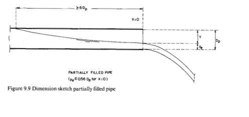
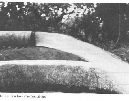
I stumbled upon the concept of fluid flow when the pipe is only partially full like perhaps when the pipe is oversized for example. I'm trying to grasp the fundamentals of this flow better but every source online is talking about open channel/conduit situations only with gravity being the primary driver. This is not relevant for me as I'm simply trying to understand it for a horizontal, closed, circular pipe.

1) Are the fundamentals different for this kind of flow? Is pressure differential not the primary motive force in this case? If not, what causes the flow here?

2) Is this considered two phase flow even if the material flowing is just water? I've seen someone call this two phase flow elsewhere. If it IS two phase flow, how so?

3) Does this kind of flow cause any fundamental problems and is to be avoided as a rule of thumb/best practice or is it OK?

4) I'm going through Crane TP-410 and I haven't seen it mention how to do calculations and what formulas to use for this flow unless I missed it. Can you please point me to a source which has this information without confusing it with gravity flow in open channels?

Thank you so much!!!

SR

 
Replies continue below

Recommended for you

Ok I'll try.

Point 2 first.
You either have a completely full pipe with liquid just going slowly or you have a mixture of liquid and gas (air in you case I think). Anything less than 100% liquid in an enclosed flat pipe where you are creating the pressure drop and not using gravity is two phase flow.

1 The fundamentals don't change but the way in which you calculate it does. Two phase flow varies a lot depending on the percent of liquid to gas and the velocity of each of them. For long lines the actual volume of the gas phase changes from one end to the other as the pressure drops and it expands.

Look up two phase flow in pipes diagrams.


3. Yes you can get slugging, vibration and mixing of the liquid and the gas.

4 I don't know of any easy formula or calculation for two phase flow. You normally need some sort of analytical flow software.

Generally speaking the open channel gravity flow is segregated or "wavy" so able to be studied and calculated. Even here though once you exceed certain flows or velocities it can transition to two phase flow in an enclosed pipe.

Remember - More details = better answers
Also: If you get a response it's polite to respond to it.
 
I don't think that you can say that open channel flow is not relevant to your case. For a situation to be classified as two phase flow it would normally be expected that both phases are continuously entering the pipe and also continuously exiting the pipe. This means that both phases are continuously traveling in the same direction in the pipe - even if they are traveling at different velocities. In the case of an oversized pipe (as would be typical with a gravity drain) there is no net flow of vapor along the pipe. If you put a pressure gauge at each end of the pipe they would read the same because it is all one common vapor space with no flow of vapor. And if the pressure is the same at both ends of the pipe, gravity can be the only cause of liquid flow.

Katmar Software - AioFlo Pipe Hydraulics

"An undefined problem has an infinite number of solutions"
 
And that's why more details / context is important here.

If all you are doing is pumping water into a closed pipe then over time it will simply drive the air out or until it reaches equilibrium. If the flow is fast enough ( about 1 m/sec) it simply sweeps all the gas out even down a vertical pipe. Too slow and it won't.

True two phase flow as katmar says, requires a flow of liquid and gas.

Basically anything once you get away from either open channel flow or single phase fluid starts getting "interesting"

Remember - More details = better answers
Also: If you get a response it's polite to respond to it.
 
Thanks for your replies guys.

LittleInch,

Fair enough.. details are everything.

I'm not saying what I have is two phase flow. I have no idea... I was more so asking if it is two phase flow. I've attached a snapshot of the exact model/situation with all the relevant details. You can see it's basically a water distribution system being pumped from a source tank into a network that goes to five destination vessels. Note that there is no elevation difference anywhere here, they're all on the same horizontal plane.

According to Rules of Thumb for Chemical Engineers by Carl Branan, to determine if a pipe is full or only partially full can be determined by Q(gpm)/d(in)^2.5 If this value >= 10.2, then pipe is full. If less than that, then it's only partially full. When I did that calculation for all the lines and branches in this model, only the most upstream segments have that value >= 10.2 and most of the downstream segments are showing partially full.

This is what spurred this thread creation...

1) Whether this would be problematic in any fundamental sense or if it would be OK.
2) Whether the flow in the downstream segments would be considered two phase flow or not. I don't see how it can be two phase flow as I can't visualize how air would get in there. The pump is drawing water from the tank source, so if no air can get in at that point, how could there be air in the partially filled downstream pipes.
3) Is static pressure differential still the driving force in these downstream segments? Or some other mechanism?

Appreciate your responses again!

 
 https://files.engineering.com/getfile.aspx?folder=8a172e4d-4642-4361-8853-fbe10ee04ffd&file=model1.PNG
Katmar said:
I don't think that you can say that open channel flow is not relevant to your case. For a situation to be classified as two phase flow it would normally be expected that both phases are continuously entering the pipe and also continuously exiting the pipe. This means that both phases are continuously traveling in the same direction in the pipe - even if they are traveling at different velocities. In the case of an oversized pipe (as would be typical with a gravity drain) there is no net flow of vapor along the pipe. If you put a pressure gauge at each end of the pipe they would read the same because it is all one common vapor space with no flow of vapor. And if the pressure is the same at both ends of the pipe, gravity can be the only cause of liquid flow.

I don't know if what I have is considered two phase flow. See my latest post where I have the details in a snapshot. Also this is not a gravity drain situation.
 
See this post from Katmar here as it may have some bearing on answering point one if you have any of the symptoms in Katmar's post.

Also note Katmar's statement on the applicability for that rule of thumb you shared and see if it matches your setup.


Where is the pump intake relative to the source vessel and how does the water discharge into the destination tanks? Are the tanks open to the atmosphere at all times or not? If you're pumping into a piping network that adequately vents the air that fills in the piping when it's empty, the pipes should run full while the pump is running - I would think.
 
jari001 said:
See this post from Katmar here as it may have some bearing on answering point one if you have any of the symptoms in Katmar's post.

Also note Katmar's statement on the applicability for that rule of thumb you shared and see if it matches your setup.


Where is the pump intake relative to the source vessel and how does the water discharge into the destination tanks? Are the tanks open to the atmosphere at all times or not? If you're pumping into a piping network that adequately vents the air that fills in the piping when it's empty, the pipes should run full while the pump is running - I would think.

This is not an existing real scenario, I'm just trying to educate myself on the fundamentals using this model. I guess the pump intake can be from the bottom of the vessel with the pipe coming out horizontally. Destination tanks are just above atmospheric pressure @ 1.1 atm in this model. The discharge would be going against the pressure of the destination tank...I guess it's going to the side of the tank on the same horizontal plane that the rest of the piping network and the tanks are in... since there's no elevation changes in the model.

Hmm... so you're saying that the piping is seeing atmospheric pressure when it's empty before the startup and so air has to necessarily be in there before the startup?
 
While most of the answers address the question asked, I would like to put the situation in a different perspective with different examples.

Case-1. Water draining from washbasin to a drain pit (without a water seal). In this case, the flow from the tap is usually less than the sealing flow calculated for the drain pipe. If you examine the flow in the drainpipe, the flow of water will partially fill the pipe until it reaches the drain pit. These flows are termed differently in various literature. Term Gravity flow is used very commonly as gravity is the driving force. Self-venting is another term used since the vapour from the pit to the basin is connected without any sealing and no vapour lock will take place in the pipe.

Case-2. Same as Case-2, except flow is now increased more than the sealing flow calculated for the drain pipe. In this case, the pipe will no longer be self-venting and water will tend to cause sealing in the line. In such cases, backing up of water will be observed. While we do the engineering design of gravity flow pipes, we design the pipe to avoid this situation. Even at maximum expected flow, Froude Number is normally maintained less than 0.3 or lower to design a gravity-flow pipe.

Case-3 Case is similar to the scheme posted by @Silverrule. For this, the following different cases are possible.

Case-3a, Flow is more than the sealing flow. During startup, any trapped air in the line will be swept aside to the destination vessel and after that, the pipe will be full of liquid. No Concern
Case-3b Flow is less than the sealing flow. However, during startup, all trapped air is vented through the vents at the high points and after that, the pipe will be full of liquid. No Concern
Case-3c, Flow is less than the sealing flow. However, during startup, trapped air is present at the high points and they were not removed. During operation, the air pockets will remain at high point and depending on the nature and dynamics of flow, these may cause varying degrees of vibration issues and in some cases no issue at all. Where there will be a problem or not is difficult to predict during design stage and hence the solution is to provide enough vents at high points to avoid air or vapour locks if the flow is less than the required sealing flow.
 
SilverRule,

It will make a big difference if the end point discharges to an open tank compared to below liquid level.

By the look of your diagram and numbers, it looks to me like the initial sections and off takes will be full and at >1m/sec will blow out any air bubbles.

However as the flow rate falls and velocity goes well below 1 m/sec you could get to a point where the pressure drop required by the flow falls below the pipe size in head required (e.g. if the full pipe liquid loss is say 1.5" wc per 100ft, but your ID is 2.1" then at that point you will probably be in open channel flow). Therefore the volume of liquid in the pipe starts to drop from 100% as air enters from the tank end. So the last part of the pipe isn't two phase, but has gone into open channel flow within a horizontal pipe. So for your calculations you have two parts - one with full flow and the second with open channel flow. Now how far back from the tank entrance you need to go isn't clear and hence why most people design a system to be one thing or the other, not a mixture of the two! Or at least for "normal operation".

This is for horizontal pipes discharging above liquid level.

For pipes below liquid level then again for truly horizontal pipes the pipes will, over time, fill completely as the air vents out from the top of the pipe.

If the flow falls to zero for a truly horizontal pipe then for pipes which discharge above the liquid level then it will, eventually, empty. Then on restart the liquid flow will fill the pipe if the flow rate / velocity is high enough. Where it isn't it will transition to open channel flow.


Remember - More details = better answers
Also: If you get a response it's polite to respond to it.
 
razookm said:
Case-3 Case is similar to the scheme posted by @Silverrule. For this, the following different cases are possible.

Case-3a, Flow is more than the sealing flow. During startup, any trapped air in the line will be swept aside to the destination vessel and after that, the pipe will be full of liquid. No Concern
Case-3b Flow is less than the sealing flow. However, during startup, all trapped air is vented through the vents at the high points and after that, the pipe will be full of liquid. No Concern
Case-3c, Flow is less than the sealing flow. However, during startup, trapped air is present at the high points and they were not removed. During operation, the air pockets will remain at high point and depending on the nature and dynamics of flow, these may cause varying degrees of vibration issues and in some cases no issue at all. Where there will be a problem or not is difficult to predict during design stage and hence the solution is to provide enough vents at high points to avoid air or vapour locks if the flow is less than the required sealing flow.

razookm,

Thanks for your input! I'll focus on the horizontal non-drain situation.

Case-3a:
No concern, I agree.

Case-3b:
1) If the trapped air in the pipe is basically at atmospheric pressure which is what it would be typically at startup, when you try to vent at the high point, it isn't going to remove any of the air from the piping is it? Removing trapped air by venting at high point makes sense only if the pressure has higher than atmospheric pressure vapor, no? So with that being the case, if you have less than sealing flow, wouldn't that flow sharing the pipe with the atmospheric air that's in the system? In this case, the pipe would never be full of liquid (I don't understand why you said that it would be.)

Case-3c:
Same as case-3b. I don't know how you would remove all the vapor by high-point venting. Only way to remove the vapor completely would be by pulling vacuum on it which is not what we're talking about. Or the other way would be, I suppose, how LittleInch said...even with a non-sealing flow, if you have a high enough velocity, that could pull all the existing air out with it into the destination tank after a while. I'm not 100% sure if this is how it works, I'm going by what LittleInch said. If that is true, I wonder how do you determine the required velocity to pull the air out with the liquid? Is 1 m/s a good rule of thumb? Also, if the air is driven out after a while, would the vapor in the destination tank not enter the pipe?

Please let me know your thoughts.

Thanks,
SR
 
LittleInch said:
SilverRule,

It will make a big difference if the end point discharges to an open tank compared to below liquid level.

By the look of your diagram and numbers, it looks to me like the initial sections and off takes will be full and at >1m/sec will blow out any air bubbles.

However as the flow rate falls and velocity goes well below 1 m/sec you could get to a point where the pressure drop required by the flow falls below the pipe size in head required (e.g. if the full pipe liquid loss is say 1.5" wc per 100ft, but your ID is 2.1" then at that point you will probably be in open channel flow). Therefore the volume of liquid in the pipe starts to drop from 100% as air enters from the tank end. So the last part of the pipe isn't two phase, but has gone into open channel flow within a horizontal pipe. So for your calculations you have two parts - one with full flow and the second with open channel flow. Now how far back from the tank entrance you need to go isn't clear and hence why most people design a system to be one thing or the other, not a mixture of the two! Or at least for "normal operation".

This is for horizontal pipes discharging above liquid level.

For pipes below liquid level then again for truly horizontal pipes the pipes will, over time, fill completely as the air vents out from the top of the pipe.

If the flow falls to zero for a truly horizontal pipe then for pipes which discharge above the liquid level then it will, eventually, empty. Then on restart the liquid flow will fill the pipe if the flow rate / velocity is high enough. Where it isn't it will transition to open channel flow.

LittleInch,

Thanks for the response! Yes, in my model, the latter/downstream 70% of the pipe segments would not be full if you go by the rule of Q(gpm)/d(in)^2.5 having to be greater than 10.2 for a pipe to be full.

If the flow/velocity in a certain pipe section of the network is low enough for the section to be less than full FROM THE STARTUP (like the downstream part of the network in my model), that means there would be residual atmospheric air in those sections from the start, correct? In that case, you wouldn't see vapor from the destination tank entering the pipe, correct?

Say that a pipe section is not full, can there theoretically be a high enough velocity that the residual atmospheric air gets removed along with the liquid flow into the destination tank?

MORE FUNDAMENTAL QUESTIONS:
1) I understand that this isn't considered true two phase flow since new vapor is continuously entering from the upstream end. But could you really call it open channel flow as you've been calling it? As I'm looking on the Wikipedia page ( it says that open channel flow is a distinct type of flow from (closed) pipe flow differentiated by the fact that open channel flow has free surface to the atmosphere. Or is it the case that you would still call it open channel flow because even though the conduit is covered it is still exposed to the (residual) atmospheric effectively?

2) katmar was saying the following earlier:
katmar said:
In the case of an oversized pipe (as would be typical with a gravity drain) there is no net flow of vapor along the pipe. If you put a pressure gauge at each end of the pipe they would read the same because it is all one common vapor space with no flow of vapor. And if the pressure is the same at both ends of the pipe, gravity can be the only cause of liquid flow.

Let's say it's not a gravity drain but an oversized horizontal pipe that is NOT FLOWING FULL... IF you put a pressure gauge at each end of the pipe, would they read the same in this case as well because "it is all one common vapor space with no flow of vapor"? If the pressure IS the same at both ends, what is the motive force that's driving the flow? If the pressure wouldn't be the same at both ends, why not? -- Could you even read meaningful static pressure in a pipe that's not full?
 
The rule-of-thumb from the Branan book comes from the article by Durand and Marquez-Lucero (Chem Eng, March 1998) and this gives a lot more detail. An alternative analysis appears in Chapter 23 of Rennels and Hudson. The Rennels and Hudson analysis predicts significantly lower flows required to fill the pipe and these are closer to my gut-feel expectation.

But what is not always made clear is that both of these analyses are limited to the discharge point of a horizontal pipe. The analysis does not apply to the pipe as a whole. Let me create a thought experiment to illustrate this point.

The R&H analysis predicts that about 25 gpm would be required to fill the discharge point of your 2" pipe. For my experiment I will use a flow of 15 gpm. If we want a 2" pipe to run half full in true open channel steady state flow we would need a slope of about 0.05 ft/ft to achieve this flow rate. Now, if the pipe is 200 ft long the required difference in height between the two ends is 10 ft. If the pipe were to be made truly horizontal we might expect that a pressure of about 10 ft (4.3 psi) would be necessary to achieve this flow. It is impossible to get 10 ft of static head in a 2" horizontal pipe so most of the pipe must run full. Both the Branan and R&H analyses predict that the discharge will not run full - but we see that most of the pipe has to run full to achieve the required pressure differential.

[Edit: In fact the pressure required if the pipe is horizontal is much less than 10 ft WC because when the pipe is full the velocity is much less. The actual pressure required would be closer to 1.2 ft WC, but the conclusion remains the same]

The only reason I go into all this extra detail to illustrate a possibly irrelevant aspect is that I want to make the point that we should not get too hung up on a definition of two phase flow. It is just a name and has no sacred definition. Probably the "two phase flow" analysis that I have used most often is for self-venting flow in vertical drain lines from condensers. In this situation the gas flows downwards (entrainment) and also upwards from buoyancy. There is no net flow of gas and so it would not meet my previous definition (3rd post in this thread) that required the gas and liquid to be flowing continuously in the same direction. But most engineers would accept that self-venting flow is a case of two phase flow. We mustn't get too hung up on definitions.

After this long theoretical excursion through the weeds, what is the practical implication for your actual problem? I would do the analysis of your whole system using standard Darcy Weisbach calculations assuming all the pipes were full, and if some of the discharge points are not completely flooded it is will not impact on your design at all. But it is good to be aware of the phenomena that can occur so that you will be able to anticipate potential problems in those situations where they are relevant.

Regarding your query on the flow required to sweep residual air from the system, the standard design criterion would be to ensure a Froude Number of at least 0.6 - although this is not a hard cut-off and you will see some variation around this number. The rule of thumb of 1 m/s proposed by LittleInch is less reliable. There have been many discussions regarding this on Eng-Tips - use the search function.

Katmar Software - AioFlo Pipe Hydraulics

"An undefined problem has an infinite number of solutions"
 
Silver rule

"If the flow/velocity in a certain pipe section of the network is low enough for the section to be less than full FROM THE STARTUP (like the downstream part of the network in my model), that means there would be residual atmospheric air in those sections from the start, correct? In that case, you wouldn't see vapor from the destination tank entering the pipe, correct?"

That's what I believe can happen.

Looking at your next point the key is the statement Katmar says which is "IF you put a pressure gauge at each end of the pipe, would they read the same" - Yes they would. If you measure head of liquid from the bottom (simple U tube) you would see the difference in water height.

So what drives the fluid flow? It's the small head difference between the top of the pipe and the final depth of water as it exits the pipe. This may not be a straight line as the volume changes as the depth rises.

Exactly like shown here :
like this

image_x6azyy.png


Flow in horizontal pipes is a subset of open channel flow where gravity and a slope is common place.

Hence why for your pipe the rule you're using works out at about 1.8m/sec - for a closed pipe that has a decent back pressure that's more than enough to blow air out, but for a pipe at an angle opening into free air you might need more than that and hence not be "sealed". Most people think that the flow is really quite high and I suppose that's the point - if you want to guarentee a full pipe that sloping and open to the air then you need to have a pretty decent flowrate / velocity.

This might be useful as well
So its the difference between this

image_h7mpo3.png


and this

image_dwrsty.png


EDIT
I posted this before I saw Katmars report.

Yes the 1m/sec is just one I use as it seems to work even for vertical down flow for relatively small pipes. If you've got less angle or flat pipe you might need less, or bigger pipe need more but you can definitely work it out.

The attached might be useful.


Remember - More details = better answers
Also: If you get a response it's polite to respond to it.
 
A picture is worth a thousand words! The diagram in the Figure 9.9 posted by LittleInch above shows exactly what I was trying to describe.

The reference that this comes from - the one that starts off "9.4 Flow from horizontal pipes" looks like a very practical and useful book - any idea what book this is?

Katmar Software - AioFlo Pipe Hydraulics

"An undefined problem has an infinite number of solutions"
 
In general, you should design applications for either full pipe flow or partial pipe flow. You don't want a situation where you are transitioning between flow pipe flow and partial pipe flow. The reason being is that weird flow characteristics occur when air is trapped at pipe elbows and high spots in the piping. Elimination of air in fluid flow requires a purge velocity which varies depending on the piping arrangement whether the piping is sloped or vertical.
 
Really good inputs from @LittleInch and @Katmar. Thanks. @SilverRule, I know you have asked me few questions which are already addressed in these responses.
 
Status
Not open for further replies.

Part and Inventory Search

Sponsor