Continue to Site

Eng-Tips is the largest engineering community on the Internet

Intelligent Work Forums for Engineering Professionals

  • Congratulations KootK on being selected by the Eng-Tips community for having the most helpful posts in the forums last week. Way to Go!

Basic radii versus basic diameter

Status
Not open for further replies.

gabimo

Mechanical
May 2, 2013
124
If in Fig 4-53/ ASME Y14.5- 2009 basic radii R40.5 is changed to basic diameter Ø81 (from radius to diameter), does this modification alter in any way the meaning of the drawing or more precise the feature definition?

Or on the same token, in Fig 4-29, datum feature B is defined with R15 basic. What would happen if R15 basic is replaced by Ø30 basic. Any changes for the tolerance zone (size, orientation/location etc.). Or there would be anything different, that you can think of, relative what is currently shown in the "means this" figure?

Thank you for the feedback.
 
Replies continue below

Recommended for you

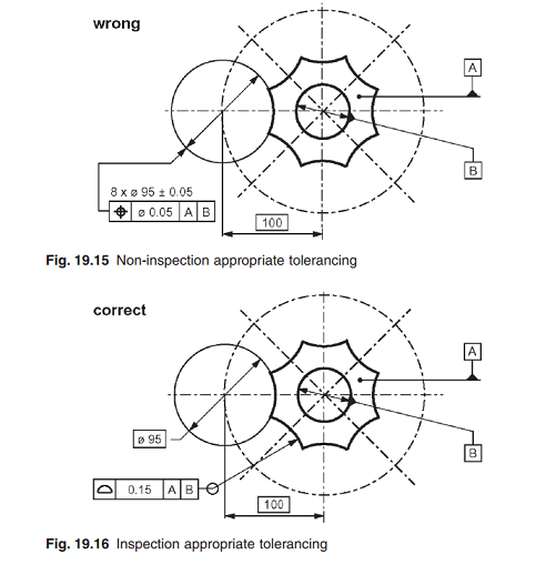
Should you keep your profile control in place, the drawing may become more confusing, but workable, as perfect theoretical diameter / radius is used to build fixture or program CMM to check profile.

Should you replace basic dim. / profile with something like toleranced diameter / position, the diameter will become difficult / impossible to measure, as the shape has no opposite points.

Capture_x0n8is.png


"For every expert there is an equal and opposite expert"
Arthur C. Clarke Profiles of the future
 
Thank you for feedback. I am not planning to replace the profile with position. I will keep profile.

I am planning only to replace the basic radius with basic diameter.

May I ask, why if I replace basic radius with basic diameter the drawing may become more confusing?
I am talking about both figures 4-53 and 4-29, conceptually the same.

 
I personally believe that as long as you can figure out where the tolerance zone is, you are OK.
Several people believe that diameter symbol should only be applied to arc larger than 180 deg.
So, to make my drawing to appeal to as many people as possible, I would do so, although there is no explicit rules.

"For every expert there is an equal and opposite expert"
Arthur C. Clarke Profiles of the future

 
I have a design where a cylindrical pin (full 360 degrees) contacts the part in question, therefore some engineers feel the need of using basic diameter instead of basic radius as originally planned.

Should I understand that wouldn't make any difference for dinemsioning and tolerancing the part from the specified two figures?
 
No, as long as you keep it basic. Although I am curious to see other's opinions.

"For every expert there is an equal and opposite expert"
Arthur C. Clarke Profiles of the future

 
Another example on what I am talking about would be figure 4-34 /2009. If R4 basic is changed to diameter 8 basic will this alter the meaning of the drawing?

Edit additions: Specially knowing that a straight cylindrical pin goes thru datum feature A, some folks think diameter basic would be a better choice.

 
I agree. Changing from a basic radius dimension to a basic diameter dimension (or to a basic CAD model) will not alter the meaning of any tolerances.


pylfrm
 
I agree too.
There would only be a difference if the dimension was toleranced by +/- or by limits.
 
Status
Not open for further replies.

Part and Inventory Search

Sponsor