Continue to Site

Eng-Tips is the largest engineering community on the Internet

Intelligent Work Forums for Engineering Professionals

  • Congratulations KootK on being selected by the Eng-Tips community for having the most helpful posts in the forums last week. Way to Go!

Basics of Grounding

Status
Not open for further replies.

NickParker

Electrical
Sep 1, 2017
413
I would like to learn about practical grounding as done in Industrial, commercial sites.

Experts insights are welcome.

1) The number of ground rods, distance between the rods of the square shaped grounding grid can be determined using IEEE- 80. Normally, where is this square shaped grounding grid could be found in the plant?
2) There are different remote locations, for example, there is a Pump room, Switch gear room, Control room in the plant. How should I connect the ground rods from these locations to the ground grid.
3) Is it that additional local ground rods be connected to the equipment's in the above said location, which is then connected to the main grounding grid (square shaped grounding grid) (or) Just the ground ground or be laid from the equipment's in the said location till the main grounding grid?
4) What is the difference between the "Earth Mat" and "Ground Grid"?
 
Replies continue below

Recommended for you

IEEE 80_2013 3. Definitions
ground grid: A system of interconnected ground electrodes arranged in a pattern over a specified area and buried below the surface of the earth.
Ground mat: A solid metallic plate or a system of closely spaced bare conductors that are connected to and often placed in shallow depths above a ground grid or elsewhere at the earth’s surface, in order to obtain an extra protective measure minimizing the danger of the exposure to high step or touch voltages in a critical operating area or places that are frequently used by people. Grounded metal gratings, placed on or above
the soil surface, or wire mesh placed directly under the surface material, are common forms of a ground mat.
In my opinion, IEEE 665/1995 IEEE Guide for Generating Station Grounding is closer.
Mainly: 5. Detailed design considerations and Annex C Division of current for small interior grids.
This standard is withdrawn actually, but P665/2016 it is instead of.
Grounding_grid_and_mat_yzmqxv.jpg
 
Grounding serves two purposes.
1. Ensures that a ground fault will draw enough current for the proper operation of protective relays.
2. Reduces step and touch potentials to safe levels.
When a cable assembly includes a grounding conductor that may be adequate to ensure the proper tripping of relays but, by itself, will often not be adequate to limit step and touch potentials on long runs.
Many plants use a robust equipment grounding scheme that far surpasses the electrical code minimums.

Bill
--------------------
"Why not the best?"
Jimmy Carter
 
I'd suggest a copy of the IEEE Green Book as an introduction. Grounding methods are much different for commercial, industrial and utility systems. Concepts are the same but practical application is much different.
 
The following are the latest books on Power System grounding:
2007
J R Dunki-Jacobs, F J Shields, Conrad St.Pierre, Industrial Power system Grounding design Handbook, Pages 565, 2007

2018
K Rajamani, Application guide for Power Engineers, Part 1- Grounding of Electrical System, Notion press.com, Pages 254,2018.

The second one is a short and practical tutorial, written by my friend, costing only six dollars.

IEEE Color Book (Green) 142-2007 has been superseded by a new IEEE standard ie
3003.2-2014 Equipment Grounding and Bonding in Industrial and commercial Power System
 
QUESTION 1.a) The number of ground rods?
RESPONSE 1.a) The number of ground rods depends upon on the design. Generally, ground rods are suggested at each corner of the grid by the fence and every 50 ft. In the preliminary design try to locate rods around the transformer. Beware if there is a rocky soil or the lower layer resistivity is higher than the upper layer, ground rods are not very effective to reduce the resistance.

QUESTION 1.b) Distance between the rods of the square-shaped grounding grid can be determined using IEEE- 80?
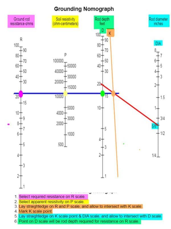
RESPONSE 1.b) As a rule of thumb, a good practice is to separate the ground rod minimum the length of the embedded rod in the ground. See the nomograph below could help.

QUESTION 1.c) Normally, where is this square-shaped grounding grid could be found in the plant?
RESPONSE 1.c) Ground grid usually is needed by the switchyard, switchgear room or major equipment. Beware that many reinforce concrete slab could be grounded to obtain an equipotential surface to help with any grounding issue. Ufer ground is another alternative to enhance the grounding needs of the facility
Grounding_Nomograph_c95ylv.jpg
 
Sazirul

Your post on 2nd March 10:00 had a link to an MWM engine, I see some potential problems with your layout, if you start a new post, I will respond to you. Which country regulations apply to you?
 
Actually, this layout was proposed form my management. They had some problem with the required space. The default layout was standard. After many discussion, Kaltimex Energy Bangladesh (pvt.) ltd provided us this layout that you have seen on my link and the construction already completed. I also had some issue with the layout but in front of management, it was nothing. Because, end of the day, they pay for everything. I feel so bad when they go like that!

Thanks

MWM TCG2020 V16k Guide | Electrical Isolator | Busbar VS Cables
 
The spacing for the ground suggest in IEEE 80 is conservative. You will need tighter grid spacing in places where it is harder for fault current to make its way into the ground, mainly the corners and edges of your grid. If you use ETAP or CDEGS or some other grounding program, you can play with the grid until just meet the requirements and not overdesign the system. You will when you play with it also see the impact that ground rods have on the grid. How many grounding rods and where they are placed is dependent on your soil. If you have conductive soil, you might just put a grounding rod next to each piece of equipment. If you have conductive soil or soil that freezes during the winter, you will have to use more grounding rod and maybe longer grounding rods to get the fault current deep into the ground. I worked on a grid in Iowa and the utility would pound three 10 foot rods down in a spot to make sure the fault current got deep into the ground during the winter. I don't know if 30 feet of rods was necessarily required but the ground usually becomes very resistive when it freezes and in Iowa, the frost depth is around 3 feet. Near the gulf, the water table is so close to the surface that ground conductors can be spaced just to make it easy for equipment to connect to it.

Other than that here are a few things that can help

Extend the grid beyond your fence if you can. The larger the grid, the easier it will be for fault current to get deep into the ground. Small grids will have a harder time getting the fault current into the ground and not riding the surface.
If you can, connect your grid to an existing grid or metallic piping if you can.
You can use GEMS or chemical salts to increasing the conductivity of the soil. Never have done this but it is mentioned in IEEE80
You can encase your ground rods in cement to increase their grounding capability. This is done in deserts and stuff and is called Ufer grounding.
Make an assumption of the techs weights. IEEE80 has calcs for 50kg and 80kg people. 50kg is less conservative. The bigger someone is the more conductive they will be.
If you can use counterpoise, you can reduce the split of the current that goes into the ground and how much goes elsewhere. Counterpoise is have a grounding conductor that leaves the substation and the fault current will go into your grid and the counterpoise and split like a current divider.
The faster your faults are cleared, the less strong your grid needs to be.
I haven't seen this in the U.S. but in some South American countries utilities go cheap on the grid and make people wear rubber boots when they enter the substation.
Sometimes it will be near impossible to reduce the touch and step potentials in some parts of your substation. Sometimes those parts will just be fenced off so people don't go into those areas.
Crushed rock is your friend. The more resistive it is or the more you have, the more the current will want to go into the ground and not track along the surface.


------------------------------------------------------------------------------------------
If you can't explain it to a six year old, you don't understand it yourself.
 
prc -

is the scope of the new IEEE standard you reference the same as the Green Book? (the new standard is only 49 pages - did they remove some of the original scope?)
 
They are transition to the DOT convention for the color books to remove duplication of content. You would see the same stuff repeated in the Red Book (Industrial), White Book (Medical), and one other for Commercial. The green book wasn't a big book. I want to say that it was around 100 or so pages but definitely more than 50. It might have been shrunk through the consolidation of material.

------------------------------------------------------------------------------------------
If you can't explain it to a six year old, you don't understand it yourself.
 
Status
Not open for further replies.

Part and Inventory Search

Sponsor