Continue to Site

Eng-Tips is the largest engineering community on the Internet

Intelligent Work Forums for Engineering Professionals

  • Congratulations cowski on being selected by the Eng-Tips community for having the most helpful posts in the forums last week. Way to Go!

Beam bearing on cast in plate 1

Status
Not open for further replies.

Veer007

Civil/Environmental
Sep 7, 2016
379
Hey guys,

I have a case where beam W690X192 bearing on cast in plate at both ends, which has 6000mm(unbraced length) span with 1550kN.m moment force per beam selection table if I go with full moment capacity of beam.

Can I divide this 1550/2 as this supported on both end? So that I have 775kN.m

Is this fine?

Thanks in advance!!
 
Replies continue below

Recommended for you

Is this possible to get a load factor for CISC? So I can check for remaining locations

This one varies for ASD, LRFD and CISC limit state

Thanks in advance!!
 
Veer007, I believe there may be some confusion here - in the OP you state that the beam is bearing on a cast in plate, then you go on to talk about determining the moment load that you need to resist. Typically a beam that is bearing on a cast in plate is designed as a pinned connection, not a moment connection. So, the only load that needs to be resisted is shear (and maybe axial if this beam is part of a floor or roof diaphragm?), in this case the shear is all transferred through direct bearing.

Veer007 said:
There is no uplift force, just have to connect for its actual reaction..

Yeah I have to determine Bearing plate to beam weld..

It doesn't sound like the weld needs to be sized to transfer any direct loads (again, unless it needs to transfer out of plane forces from the wall into the beam/diaphragm). The weld is going to simply provide structural stability by creating a positive connection between the beam and the bearing plate.
 
I am totally confused now, don't we have to consider these reactions force due to live load, dead load or snow load when the beam bearing cast in plate [COLOR=][/color]
IMG_20200930_201924_lvlmhb.jpg


Thanks in advance!!
 
I tried to point this out previously. If the beam is sitting on the bearing plate, and all loads are gravity only. There's nothing I see that requires specific loads to size. It's just providing a reasonable connection to keep the beam in place during construction and incidental lateral loads.

Do you have anyone senior in your office you can talk to about this? It seems fairly fundamental.
 
I was told that when beam directly bears on cast in plate there is no vertical shear that we have to design weld as dauwarda told

What was my concern is, is there nothing we have to consider when the beam carries UDL.

I thought udl create some reaction at both ends even it directly bearing on cast in plate, is it wrong?

Thanks in advance!!
 
Veer007 said:
Is this possible to get a load factor for CISC? So I can check for remaining locations

This one varies for ASD, LRFD and CISC limit state

Load factors are specified in section 7.2 of CISC Handbook of Steel Construction. They are different than the factors in AISC. You must have that information at hand.

Veer007 said:
I am totally confused now, don't we have to consider these reactions force due to live load, dead load or snow load when the beam bearing cast in plate [COLOR=][/color]

Your question is not clear. In what way are you totally confused?

Veer007 said:
I was told that when beam directly bears on cast in plate there is no vertical shear that we have to design weld.

What was my concern is, is there nothing we have to consider when the beam carries UDL.

I thought udl create some moment at both ends, is it wrong?

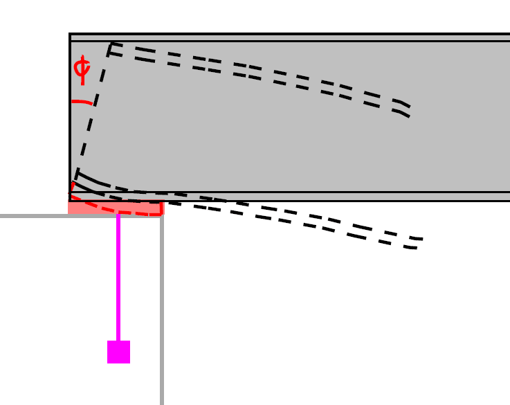
When the beam is loaded, it deflects at midspan and rotates at each end, i.e. the beam slopes slightly at the bearing point. If it is bearing on a large base plate, the beam will tend to bear near the edge of plate so that the reaction is not centred on the bearing area. Some engineers make allowance for this by using a square bar at the intended point of bearing. Others do not. If the EOR did not specify something like that, you can assume that it is not required.

BA
 
If it is the case, Can I ignore all support reaction (DL LL SL), and provide weld as per J2.4 table AISC using thinner part joined?

All this reaction can be arrested by Direct bearing, right.

Thanks in advance!!
 

Do I have to design weld size by using the support reaction provided by EOR or I don't? As this bears on cast in plate both ends

Yeah, no lateral or uplift force, just have to design for support reaction during construction

All load can be transferred through Direct bearing, right?

Thanks in advance!!
 
Aplogies, I didn't get your point, initially jayrod12 told that.. thanks BAretired too..

Can clear Above my doubts? Just for make sure

Thanks in advance!!
 
This is what I concern about, that's why I asked do I need consider the loads..
Screenshot_20201001_161224_hqg1mv.jpg


Thanks in advance!!
 
Veer007,

After 30 some posts, I am getting more confused on what is the problem. Let me try to sort it out.

You started with a 6m long W690x192 beam simply supported on "cast-in plate" at both ends, the beam is unbraced, and the reaction loads are 975kN DL, 300kN LL, 80kN SL, which turns out a factored reaction of 1710kN (per Jayrod). From that, the uniform load, Wu = 1710/6 = 285 kN/m, and Mu = 285*62/8 = 1282.5 kN-m < Mr = 1550 kN-m. By inspection, beam shear capacity is adequate, Vu << Vr = 2230kN (per BA).

For beam to plate weld, you can conservatively design the weld for 20% of the maximum reaction at each end, 171kN. Hope this helps.
 
Design of connection should match with the assumptions made during the analysis and design of the frame sections.
Such as in your case, if the beam is designed for a simply supported support condition then the connection must allow the rotation. For example in the snap shot you shared, if let’s say your bearing plate is anchored to concrete with two bolts only, the bearing plate will simply rotate with the beam. Because there is no force to hold it down.
image_z2bczv.png


That being said, I just want to point out one more thing, a simply supported beam with bottom flange "rigidly" connected to a very "rigid" support (high lateral stiffness) will most probably have some significant horizontal reaction from analysis. Refer to the following Fig. (courtesy of csi knowledge base). This is one of the thing you should discuss with the EOR.
image_wfjkl6.png


which, again you can avoid if you follow this advice.

Celt said:
If your connecting to cast in plates on both ends of the beam make sure you allow for one end to have some slip. Any temperature swing after the beam has been placed will rip one of the embeds out to the wall if it is rigidly attached to both of them.]
 
I question the wisdom of welding the beam to the embed plates at all. Welding is unnecessary to resist gravity loads. All that is required, is a nominal connection to hold the beam ends in position. Consider instead, using anchor bolts with slotted or oversize holes in the beam flange to accommodate thermal movement. Otherwise, thermal expansion and contraction could damage the concrete foundation. Needless to say, this should all be with the approval of the EOR.

And while you are talking to the EOR, it might be a good idea to ask him about using a plate between the embed plate and beam to avoid bearing down on the inside edge of the base plate. Hopefully BP-14 has been designed to spread the beam reaction in accordance with the code.

BA
 
Yes, agree that welding both ends is a bad call. Weld one end, provide guide on the other, if weld joint is desired.
 
The design related concerns about welding the beam to the embedded plate are valid. With reference to the first image posted by Blackstart123, if you keep the weld near the edge of embedded plate and away from the end of the beam, the end of the beam should be able to lift up slightly and allow some end rotation. As noted by others, you only need a nominal connection to secure the beam (short weld length, no need to weld the entire bearing length). You still need to check the bearing strength of the beam.

Welding to the embedded plate has practical issues. It is extremely rare (where I practice anyway) to have an embedded plate set accurately enough to connect a beam directly without some adjustment. If your embedded plate is too low you can shim, which may double your field welding depending on the shim thickness. If your embedded plate is too high you might have to cope the bottom of the beam and weld a bearing plate to the beam web to replace the bottom flange. If the embedded plate is not level, you might need tapered shims depending on your bearing requirements.

A better detail as noted by BA is to use anchor bolts with oversized holes. Rather than embed the plate in concrete, weld it to the bottom of the beam (if required, if the beam is wide enough this might not be necessary). Then you can bolt the beam to the concrete with an allowance to grout below the beam. It takes the pressure off the concrete guys to get their embedded items perfect and it eliminates field welding - all around its a better detail.
 
If there is no specific reason that require the bearing plate be flush with the finished surface, don't do it. You can:

1) Embed the anchors, then install the bearing plate, and weld the beam to the bearing plate, or
2) Same as 1, but weld the bearing plate to the beam prior to installation.
3) Use post installed anchors.

Also, bearing pad shall be set back from edge for a small distance (usually 1/2" increments).
 
Status
Not open for further replies.

Part and Inventory Search

Sponsor