Eng-Tips is the largest engineering community on the Internet

Intelligent Work Forums for Engineering Professionals

Beam bending refresher 2

rcfraz37

Mechanical
Oct 9, 2024
5
0
0
US
So its been a while since I did beam bending back in school and now I'm having some trouble.

The regular equations, I believe, assume fixed ends, at least the ones I can find. Trouble is I am looking for the length by which a beam gets shorter as it bends, and my end points rotate.

See pic
A is rigidly affixed translationally but allows the beam to rotate freely. B prevents Translation in the Y direction but no other Direction.

I'm trying to make my design driven because we keep changing materials so I'm going with F= force (assuming a uniform load across the length) L= length I=moment of inertia and E= modulus of elasticity.

I tried finding the deformation with (5*F*L^4)/(384*E*I)=d. and then the slope with w*L^3/(24*E*I). and using those to back out the geometry of the arc but the math isn't right.

Am I heading in the right direction?

Any help would be a life saver
 
 https://files.engineering.com/getfile.aspx?folder=15f48676-a670-4e27-a58b-969236dec5b9&file=beam_bending.png
Replies continue below

Recommended for you

?? why did the large displacement model give such different answers for the mid-point deflection ?

small displacement model ... "Midpoint deflection (X, Y, Rot°) of (0, -0.998, 0°)."

large displacement model ... "Midpoint deflection of (-1.05, -3.99, 0°)"

"Wir hoffen, dass dieses Mal alles gut gehen wird!"
General Paulus, Nov 1942, outside Stalingrad after the launch of Operation Uranus.
 
how does this idea (of taking the rotation of local section into account, by taking components of the load) fit with the loading ? fit with the theory ? (maybe with large displacement analysis ?)

is the applied UDL vertical or normal ?

if we're going to have the axial component or the reaction, then we'll also have a reduced shear component, yes?

"Wir hoffen, dass dieses Mal alles gut gehen wird!"
General Paulus, Nov 1942, outside Stalingrad after the launch of Operation Uranus.
 
Non linear beam analysis by hand is possible but rather tricky, typically iterative- that's why the SAE design guide for leaf springs is full of nomograms

Otherwise it's a case of building a model in a different software and comparing the results.

rb1957's point is interesting, I'd hope the loading remained vertical throughout, reaction force at the pins tell you it was..

"No one seems to be considering the neutral axis" - a curious statement, it is mentioned twice before your post.

Cheers

Greg Locock


New here? Try reading these, they might help FAQ731-376
 
GregLocock said:
Now increase A but leave I the same.
Unfortunately I had a hardware problem almost immediately after my Strand7 run, and ended up corrupting the software. Then I discovered that the company no longer offers a "demo version". So further analyses are impossible.

rb1957 said:
Why did the large displacement model give such different answers for the mid-point deflection?
Because I deliberately set it up that way.

rb1957 said:
Applied load vertical?
Loads were applied vertically, to the nodes.

mfgenggear said:
What are the units?
As I parenthesised near the start of my post, I merely used non-identified but CONSISTENT units. Beam cross-section is 1x1 square.


[sub][ ]—————————————————————————————————[/sub]
[sup]Engineering mathematician / analyst.[ ] See my profile for more details.
[/sup]

 
sorry, Greg. One of the limitations in the Strand7 demo version is (¡was!) that it does not have any way of saving any aspect of a model. When you close the program everything evaporates instantly.

[sub][ ]—————————————————————————————————[/sub]
[sup]Engineering mathematician / analyst.[ ] See my profile for more details.
[/sup]

 
probably the most important factor would be including shear deflections. I don't know if we know enough about the situation to determine it is a large displacement problem. OP ??

"Wir hoffen, dass dieses Mal alles gut gehen wird!"
General Paulus, Nov 1942, outside Stalingrad after the launch of Operation Uranus.
 
rb1957.[ ] You may well be right about the potential significance of shear deformations in the beam, but the only way I can think of to investigate that would be modelling the beam using a large number of three-dimensional cuboid-shaped elements.[ ] This would be megaparsecs beyond the model-size limits of my now-gone-forever Strand7 demo software.

Re the OP's need for a large displacement analysis, his posts suggest to me that this is the issue he is trying to explore.[ ] It would be nice if he could confirm.

[sub][ ]—————————————————————————————————[/sub]
[sup]Engineering mathematician / analyst.[ ] See my profile for more details.
[/sup]

 
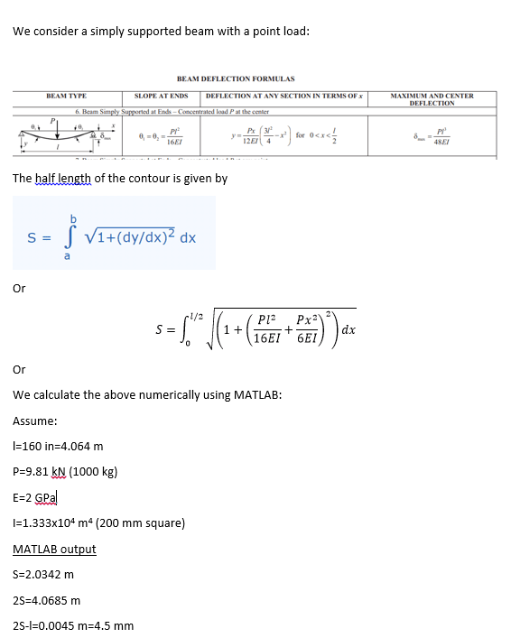
I have done a simple beam calculation as below:
beam_length_mhkfxs.png

So there is about 4.5 mm elongation
Interpretation of this using Timeshenko to be seen

Engineers, think what we have done to the environment !
 
I think the OP has left the room....

Asking myself about torsional buckling due to imperfect actual load application on a long slender member?
 
What would be interesting is to know at what deflected shape would the beam have to be in for non linear effects to start having a significant effect. Knowing that and what change in length is actually needed for the design to function would be interesting.
 
Back
Top