Continue to Site

Eng-Tips is the largest engineering community on the Internet

Intelligent Work Forums for Engineering Professionals

  • Congratulations KootK on being selected by the Eng-Tips community for having the most helpful posts in the forums last week. Way to Go!

Beam Load Spanner Design

Status
Not open for further replies.

logann

Mechanical
Apr 3, 2024
7
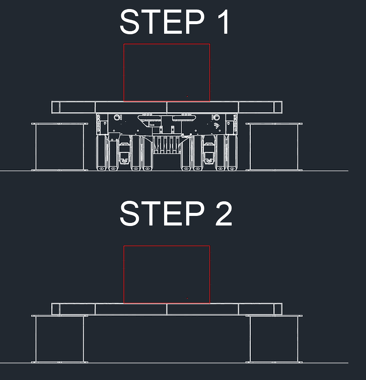
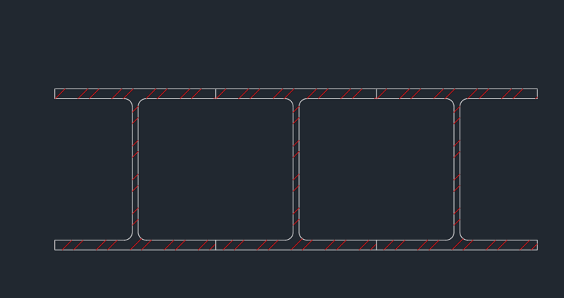
Hello all - new here but looking to learn! We are looking at a scenario where we are wanting to use beams, with internal gussets and welded seams as load spanners. I'm curious how to properly set up calculations to see what maximum allowable loads would be. There are a few different sizes of beams we are looking at running numbers for, as well as different numbers of beam combinations for a couple of scenarios. Picture below for reference.

Any guidance to some reference material or other reading material would be greatly appreciated!

BEAMS_jrkphf.png
 
Replies continue below

Recommended for you

When you say "load spanners" I'm assuming you mean 'beams that span a gap with load on them'?
We would just call them beams

If I've understood your question correctly, you're asking for the basics of how to design a beam
That's not really what this forum is for but if you google 'how to design a steel beam' you'll probably find resources to get you started
As to the relevant load combinations etc - that's a mixture of working out the correct loads from either your local Code or relevant manufacturer (if supporting machinery etc) and going to your local Code to get the combinations required

The tricky part with your installation is likely to be how to force your three side-by-side beams to act as one member
As you've highlighted, some sort of welded or bolted gusset system will likely be your answer
There is a lot of potential nuance to this though as the connection details will influence whether your members behave compositely, as three equally-contributing beams, or some combination thereof
The details will also affect the potential for out-of-plane buckling of your beams, or local buckling of flanges etc
However, the nuances of these details are probably lost if you don't know how to design a beam in the general sense as these effects are a downstream consideration from the global beam design equations
 
Your note about making the side-by-side beams act as one member is accurate - that is my goal. I've found many resources regarding beam designs, but none clearly define how to go about making them act as one. I'm trying to do this without any analysis software at my disposal, and so I figured I would ask here for resources or guidance. Like you mentioned, there are quite a few nuances that need to be considered and all adding an additional layer of complexity in their own.
 
Ok, if you want them to act side-by-side then I'm going to assume you're looking for 3x the beam strength rather than composite action (composite action would only really be applicable for sideways loading here anyway - you'd need to stack them for composite capacity)

The first nuance is: where is the loading applied?
If this is a heavy vehicle with a wide tire then you're probably loading all 3 beams relatively equally, so your connection is more for displacement compatibility than load sharing
However, if you're going to be directly loading the middle beam (say a narrow tire, or a hoist fixed to one beam only) then you'll need to detail your connections to transfer vertical load
Fully welded stiffeners is an easy way to do this but probably practically very difficult to do - I think you'll need to weld stiffeners to each member then bolt them at the overlaps (though even that is going to be very difficult - how do you get inside the beam cavity to bolt anything?)

You could lay transverse steel members/plates that have sufficient bending capacity and stiffness to transfer these vertical loads?
Or lay a longitudinal running deck of welded steel plate
Or use some sort of bolted cleat arrangement - I'd be considering tension tightened bolts though if vertical loads are high

The second nuance will be around the restraint conditions of the beams
Welding stiffeners between the 3 beams will help to prevent/mitigate some failure modes, though won't remove all of them
You still have the risk of all 3 beams buckling sideways in the same direction but I would expect that your cleats, if welded to the top and bottom flanges on the respective beams, would pretty much remove your local flange buckling and torsional failure modes
 
logann - you need to define the support and loading conditions on these beams. both down the length and across the width.

you mention internal gussets - what configurations are you thinking? how installed? and why needed?
 
Greenalleycat - ideally, load case would always be centered and equally distributed. It would be up to our department, in conjunction with the client, to ensure correct measures are taken to ensure as close to evenly distributed loading as possible. I initially called them spanner beams because the application we're wanting to use them for is for the below scenario. Basically we have a couple of self-propelled modular transporters that would carry the load centered on the beams to an arbitrary staging location. Once in position, the trailers would lower the load onto the staging cans and walk out from underneath the beams and the beams and cans would support the load at that point.

swcomposites - the internal gussets are hard to determine exactly at this point and are part of some ongoing internal discussions as well. We are thinking welded where we can because of strength purposes, but we are not settled on that either. Main concern at this point is how to configure beam loading capacity for any combinations of beam size and number of beams we want to run for a given project.

BEAMS_xtah2u.png
 
instead of I-sections that are touching at the flanges, why not something like:
- thick flat top plate over the entire area, +
- I-section beams welded to the top plate down the length of the upper flanges, spaced apart so that there is sufficient access between the lower flanges to weld or bolt transverse members, +
- transverse members welded or bolted to the longitudinal beams
 
Status
Not open for further replies.

Part and Inventory Search

Sponsor