sam3990
Civil/Environmental
- Jun 30, 2024
- 7
Hi all
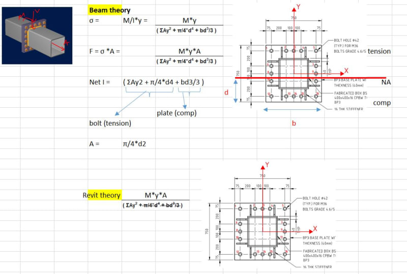
I need some help in design of beam bolted connections. The SHS is 400x16, splice plates are 750x750x40mm thick and bolts M36. Lets say a moment of 100 kNm applies. By simple calculations
1) if i apply the revit theory, My/Σy2, i get a maximum bolt force of 31.91 kN. The net moment of inertia is only due to the bolts considering neutral axis at centre of the bolt group (which is 750/2=375mm)
2) If i apply beam theory, considering 40thk plates to be rigid enough, considering neutral axis at a depth d, so the net moment of inertia of the entire system is calculated using compression bearing area of the plates above neutral axis plus moment of inertia of tension bolts below neutral axis.
Using this I'm getting neutral axis = ~100mm and maximum bolt force 23.5kN.
Which one can be considered a logical method in the given scenario? Attached an image to give a summary.

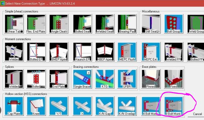
I tried to validate using RAM connections but it lacks the capability to check splice as such. Can someone recommend a good way to validate these results?
I have scoured the net for Australian Tubular design guide 24 but havent found anywhere. Can someone please share if you have. Many thanks in advance. Cheers.
I need some help in design of beam bolted connections. The SHS is 400x16, splice plates are 750x750x40mm thick and bolts M36. Lets say a moment of 100 kNm applies. By simple calculations
1) if i apply the revit theory, My/Σy2, i get a maximum bolt force of 31.91 kN. The net moment of inertia is only due to the bolts considering neutral axis at centre of the bolt group (which is 750/2=375mm)
2) If i apply beam theory, considering 40thk plates to be rigid enough, considering neutral axis at a depth d, so the net moment of inertia of the entire system is calculated using compression bearing area of the plates above neutral axis plus moment of inertia of tension bolts below neutral axis.
Using this I'm getting neutral axis = ~100mm and maximum bolt force 23.5kN.
Which one can be considered a logical method in the given scenario? Attached an image to give a summary.

I tried to validate using RAM connections but it lacks the capability to check splice as such. Can someone recommend a good way to validate these results?
I have scoured the net for Australian Tubular design guide 24 but havent found anywhere. Can someone please share if you have. Many thanks in advance. Cheers.

