Eng-Tips is the largest engineering community on the Internet

Intelligent Work Forums for Engineering Professionals

Beam Over Column Connection 1

Status
Not open for further replies.

Veer007

Civil/Environmental
Sep 7, 2016
379
0
0
IN
Hey Guys,

I have the case, where beam bearing on column cap plate which has 360kips as shear and no moment force. Shear force will be satisfied by using direct bearing. Is this necessary to design cap plate thickness and number of bolts still? If yes any way to design? Or just I need to provide cap plate thickness same as beam flange?

below from AISC (Hollow StructuralSection Connections) states cap plate thickness should be min of beam flange.

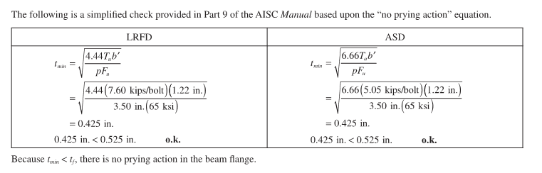
[highlight #EF2929]"The following is a simplified check provided in Part 9 of the AISC Manual based upon the “no prying action” equation.
Because tmin < tf , there is no prying action in the beam flange."[/highlight]

Capture_s3kkeb.png


Beam flange thickness is 2.75"

Document1_l16pij.png


Thanks in advance!!
 
Replies continue below

Recommended for you

human909 said:
They aren't justifications to argue it is a pinned connection.

You say that because you're focused on whether or not the joint itself is a literal hinge. If you expand your consideration to focus on whether or not the joint's rigidity will meaningfully draw moment to the affected member, then it becomes apparent that anything that limits the moment attracted to the joint tends to support designing the members as though the joint were a hinge. Moreover, regarding item #3, how is a column's ability to yield itself into a literal hinge partway through the load history somehow not a justification for assuming pinned behavior? I'd say that's pretty on point.

human909 said:
Like I have said before. I've see this type of connection design go wrong in such a way that the column underneath was visibly bending like a banana due to the induced moment.

Yes, I recall. Above, I linked to that thread primarily because it contains the example that you've tabled again here. That single, extreme example changes nothing in my opinion. There will always be extreme conditions requiring careful designer attention and making rules of thumb non-universal. Judgement: that's why we get paid.
 
BAretired said:
I think I agree with the intent of the above, but would change the word curvature to slope. For the column, the slope at the top determines the moment. For the monster beam, the moment is negligible.
Valid point regarding slope/curvature I'll try to be more accurate in the future. Regarding the monster beam, it doesn't matter if the beam is a monster if the span is also long.

KootK said:
That single, extreme example changes nothing in my opinion.
That is true. But it is an example that I had on hand.

I've now examined the scenario using these members and assumptions on their length. 20m,W40-503, 7m, W12-102. Loading is UDL of 160kN/m. In the case of a pinned connection the member passes the code used (AS4100) by 120% 55%. In the case of a rigid connection it passes the code by 22%.

That is a SIGNFICANT difference that cannot be ignore. Feel free to run the numbers with the code of your choice.


(Checking the rigidity of the connection can come later. It requires more work.)
 
human909 said:
They are all good justifications on why the connection you design may not result in a worse outcome from a strength perspective. They aren't justifications to argue it is a pinned connection.

Just thought of a #4 as well, although it's admittedly arcane. At Pcr, the flexural stiffness of the column drops to zero. A thing in compression has its flexural stiffness reduced relative to that same thing not in compression. So, in this sense, the more load the beam delivers, the less flexural stiffness the column has, and the more the joint resembles a literal pin.

Obviously, I'm not suggesting that anybody interested in profit attempt to factor this effect into production design work. That said, the fact that the joint becomes more pin-like with every increment of axial load added to it is a convenient feature of the setup.
 
Well it sounds like you will be hard pressed to be persuaded otherwise. Ok, I'll put in the hard yards... (To your credit KootK you are often the one putting in the hard yards :) )

-I've already calculated an almost 50% drop in column capacity 20% drop in column capacity cause by the induced moment of a rigid connection. Feel free to do it yourself to your own code and with alternative but sensible beam lengths.
-So it comes down to connection rigitiy. I'll try to test this and post the results. Do you want to pick a length for the W40 beam? That is the only unknow here.
 
human909 said:
To your credit KootK you are often the one putting in the hard yards

Thanks. It is quite rare, however, for me to do any numerical hard yards. I enjoy theory and sketching details primarily. I don't dispute that numerical work has its place as a form of evidence; it's just not my personal sweet spot because:

1) I take little joy in cookbook design via spreadsheet / software runs. Real work has enough of that.

2) When it comes to validating theoretical ideas, I rarely accept anybody's work other than my own unless I spend the time to vet the snot out of it. That tends to involve a lot of heated back in forth that eats time and, again, brings me little joy.

human909 said:
Do you want to pick a length for the W40 beam?

If you're going to go to the trouble of taking this further, I think we should do it with with OP's real spans and loads.

human909 said:
So it comes down to connection rigitiy.

Not for me, yet. See #2 above.
 
It is not necessary to do it with real spans. The slope is whatever it is. If the beam length is very long, the end slope will be large. The moment in the column varies directly with the slope, let's say θ.

If the bottom of the column is pinned and its height is 'h', the moment at the top is M[sub]top[/sub] = 3EI*θ/h. Makes no difference to the beam as it has practically zero moment at the end. It makes a huge difference to the column, however, as M[sub]top[/sub], together with the beam reaction produces lateral deflection and a P-delta effect.

For the beam, the connection is close enough to be called a pin. For the column, the connection is not a pin!

BA
 
BAretired said:
For the beam, the connection is close enough to be called a pin. For the column, the connection is not a pin!
Excellent point!

And like I have calculated in the example above as far as the column is concerned this distinction may be extremely critical to the column's design capacity.

Kootk said:
Thanks. It is quite rare, however, for me to do any numerical hard yards. I enjoy theory and sketching details primarily. I don't dispute that numerical work has its place as a form of evidence; it's just not my personal sweet spot because:

1) I take little joy in cookbook design via spreadsheet / software runs. Real work has enough of that.

2) When it comes to validating theoretical ideas, I rarely accept anybody's work other than my own unless I spend the time to vet the snot out of it. That tends to involve a lot of heated back in forth that eats time and, again, brings me little joy.
I totally accept that stance and largely feel the same way. Though every now and again I like to put my numbers/computers to work to check my words.
 
If the beam was designed in accordance with code, the deflection is likely between L/240 and L/360, let's say L/300. That would have an end slope of 0.0133. If EI[sub]y[/sub] for the column and height h are known, the deflection can be calculated. If the beam reaction is known, the P-delta effect can be calculated.

If the EOR is expecting a pin connection, it can be achieved, but it may be more economical to reinforce the column to carry the combination of axial load and bending moment.

BA
 
I ran a connection check of Kookt's drawing. In a similar approach to what is described here:

Results were as previous discussed and more accurately describe by BAretired.
-The connection has a calculated stiffness of 24,000kN/rad
-As far as the column is concerned this is a rigid connection, the column takes significant moment and its design capacity drops by almost 50%. If this column has been designed for axial load only this is a significant problem!
-As far as the beam is concerned the connection might as well be flexible

Below is the FEA for the connection and a basic moment/deflection diagram for the two members:
Connection_nsunsz.png
 
Neat. Questions:

1) How is the flexibility of the bolts captured in such a modelling exercise?

2) Do you not feel that your element sizes are a bit large for something like this? See the sketch below for the mesh on your model (left) versus the mesh shown in the referenced web page that you provided on your method (right). Obviously, if the mesh size is too large, the model will fail to capture flexibility adequately. I'd think the mesh size that you've shown adequate for, say, a beam taken as a whole. But perhaps not a connection where the important distances are small.

C01_boljzq.jpg
 
I did a little old school hand design to get some alternate ideas on the table. You kinda have to speak AISC manual design to read this easily and I apologize for that. Also, given that it's 11PM here, there's surely a mistake in there someplace in need of finding. Without further adieu:

1) OP's axial load @ 360 kip.
2) Beam end slope @ L/300 per BAret.
3) Column @ 7m per Human909.
4) No account whatsoever given to connection flexibility.
5) No account given to column stiffness reduction associated with axial compression.
6) Conservatively estimate column moment assuming a column slope matches beam slope with zero moment at the beam end.
7) Load eccentricity is a paltry 2.20 in. One would certainly hope that the original column design included more eccentricity than that.
8) Connection moment increases interaction equation by 43% when column top restraint is ignored (K=1.0)
9) Connection moment increases interaction equation by 19% when column top restraint is conservatively accounted for (K=0.8).

C01_jizy9a.jpg
 
KootK said:
Neat. Questions:

1) How is the flexibility of the bolts captured in such a modelling exercise?
24mm steels bolt x2. So they stretch as per the bolt stiffness. NOTE: They are not pre-tensioned! I would have preferred to add pretension but the model was completing with 0 deflection and zero stress when using pretension. A brief google shows that other people have had issues with this FEA on pretension. Obviously adding an appropriate amount of pretension will make the connection more stiff.


KootK said:
2) Do you not feel that your element sizes are a bit large for something like this? See the sketch below for the mesh on your model (left) versus the mesh shown in the referenced web page that you provided on your method (right). Obviously, if the mesh size is too large, the model will fail to capture flexibility adequately. I'd think the mesh size that you've shown adequate for, say, a beam taken as a whole. But perhaps not a connection where the important distances are small.
The mesh size varies according to the detail. Additionally I manually changed the mesh size to be quite fine around the bolts to ensure the detail of the bolts was captured properly. I found this to be the best compromise to get it working satisfactorily. (I've now started a run with fine mesh throughout. It might struggle, or maybe it will complete in 30minutes....)

EDIT:
Ok it only took 15mins run time. Deflections increased by 3%. Here is a zoomed in shot on the bearing interface. Deflection obviously exagerated.
Connection2_vhswtn.png
 
Let's hear it for fast computers...

For me, much comes down to that 2.20 in eccentricity of load. If the moment generated by conservatively assuming full fixity in the joint would only produce a modest eccentricity that designers ought to be considering anyhow, I deem the whole thing not of much concern from a connection design perspective. The EOR shouldn't realistically be expecting less moment than this even with clip angles mounted to the web of a pass through column.

Another interesting feature of my number crunching exercise is that, the higher the axial load becomes relative to max, axial only capacity, the less impact the moment has on the overall design for the case where column top restraint is accounted for. In the analysis below, I've jacked the axial load up from 360 kip to 650 kip, or about 95% of pure axial capacity. At that level, the impact of the moment in the joint represents only a 3% increase. And that's with all of the other sources of conservatism still in play.

C01_j8cdr6.jpg
 
Jumping in late to the party so don't know if it was directly discussed, but does the provisions of J.1.4 compression members with bearing joints cover the design requirements? using a moment and shear from a transverse load equal to 2% of the compressive strength?
 
I thought about extending the column upward and connecting the beams into the column web, but the flanges of the beam are much wider than the column and 2.5" thick, so that idea won't fly. Maybe the column could be rotated 90[sup]o[/sup] and connect the beams to the flanges. That would be the more typical way of doing it, but the EOR would have to approve. A little more eccentricity that way, but moment would be about the major axis. The depth of column is almost equal to the flange width, so it doesn't take any more floor space that way.

BA
 
BA,

The beam flanges can be coped to fit into the column at added cost. Also, it looks like there is a beam in the transverse direction, framed into the W40 by the double angle stiffener. Anyway, the OP's scope is to design the connections, beams and column were designed by others.
 
KootK said:
Let's hear it for fast computers...
No good if the user is sloppy.... [pc1] [sad] My capacity caparison earlier had an error where I wasn't comparing apples with apples. I see a ~20% reduction in capacity not the 50% I was more alarmed about. (I've edited my previous posts with strikethrough) If you start shrinking the span from 20m you eventually reach a point where you start increasing capacity due to the rigid connection reducing the effecting column length (as you I believe have already mentioned).
(I'm satisfied that the FEA analysis was suitably done.)

KootK said:
I deem the whole thing not of much concern from a connection design perspective. The EOR shouldn't realistically be expecting less moment than this even with clip angles mounted to the web of a pass through column.
I now agree with this conclusion.
 
r13,

I don't believe anything is written in stone. If the idea is sound, perhaps the OP can prevail upon the EOR to consider rotating the column. If not, it was worth a try. I don't know much about the transverse beam, but I would think that the W40x503 is the main beam bearing on that column.

BA
 
calm after a storm, After so many replies, What I understand is for this larger beam if the connection will be designed as pinned, it will allow some rotations so that there is no effect on the column. Also, we know all pinned connection is are not completely pin, it will act as slightly rigid too. right?

I forgot to give some info that column height is 12 feet and beam length is 50 feet

I don't have much knowledge about design main members like columns and beams, but it's my responsibility to design connections.

So you guys recommending to rotate column, so that it will arrest moment on its major axis while now column located transverse to beam web, is it?

So finally can I go with the Kootk solution? as adding stiffener. But Still, it's required if we designed this as pinned?

Thanks in advance!!
 
Status
Not open for further replies.
Back
Top