Continue to Site

Eng-Tips is the largest engineering community on the Internet

Intelligent Work Forums for Engineering Professionals

  • Congratulations KootK on being selected by the Eng-Tips community for having the most helpful posts in the forums last week. Way to Go!

Beam stress and deflection calculation two equal loads

Status
Not open for further replies.

davesen

Mechanical
May 4, 2015
9
I am attempting to size either an aluminum or steel channel to raise a load. The attachment shows this situation with two equal loads and two equal forces utilized to lift the load. The loads and forces are symmetrical as shown. The lifting force is under the channel pressing on the web. The channels are horizontal and turned with the legs facing down.

Using stress and deflection formulas I attempted to validate if a steel and/or aluminum channel will work for this application. The sizes are all noted on the diagram and the formulas for each are presented. It appears that I am significantly undersized looking at the bending stresses, but the deflection calculations do not seem to work.

At the very bottom of the calculations I also completed a deflection calculation using a rectangular box tube which I know to be very strong and actually has almost no deflection in this application. I had a box tube handy so I physically tried it.

I need to use a channel to eliminate the box tube height for this application.

Can someone review and tell me where my calculations are in error?

Thanks, Dave
 
 http://files.engineering.com/getfile.aspx?folder=9c141f36-3c1e-4926-b9df-1a8d07d18747&file=stress_and_deflection_on_channels.pdf
Replies continue below

Recommended for you

I`m not familiar with the equations that you're using and cannot comment on those, but you do have an error in your units.
In the deflection calculation for steel, youre using W=1000 lb and E=29000 kips/square inch.
This puts your deflections too high by a factor of 1000.
 
This to me is a spreader bar, and it is not clear exactly what is going on. You are lifting something which is attached at the ends, and you are lifting from the point closer to the center? Typically in a spreader bar, you will have the lifting points right above the lifted load attachment points, this would eliminate bending from your lifted load (ie W and F should be right above each other). This may not be possible depending on your situation.
 
Do yourself a favor and pick what units you want to use and then force yourself to use them from here on out. Use ft or inches/kips or lbs. Translate all your units in the begining
 
Or use Mathcad, no need to worry about conversions!
 
Thanks guys, yes the KIPs error is the one I was missing in the deflection calculation. Also correct I do need to offset the upward lifting force by 5" inboard. Regards,..
 
your equations are Way off ...

bending stress is not W*(c-u)/Z; it could be W*c/Z where "c" is the distance between the load and reaction (= 5"). so your Al stress should be 1000*5/0.692 = 7.2ksi

deflection are in microns (10^-3inches) ... you've put E for Al as 10,000 (it is 10E7psi)
I think there's another error there too, cause I don't see a beam working at 7ksi deflecting 0.5", but it is a long beam, so ... maybe

another day in paradise, or is paradise one day closer ?
 
You can derive the equations for moment and deflection for this system in a few simple steps:

Sketch the shear force and moment diagram. The shear force between the two supports is zero, so the moment is constant and equal to the cantilever moment (WC), and this is the maximum moment in the system (not W(c-u)).

The beam is symmetrical, so slope at the centre is zero, and slope at the supports = Curvature x u/2 = WC/EI x u/2

The deflection at the end loads, relative to the support = deflection due to slope at support + deflection due to cantilever deflection =
(WC(u/2)c + Wc^3/3)/EI = (Wc^2/EI)(u/2 + c/3)

I get -0.062 in for the aluminium channel. Obviously the deflection at the end of the beam will be more than that.

Putting it into Mathcad (or anything else) might pick up the units error, but it won't pick up the errors in the equations, and it won't help you understand what is happening.

Doug Jenkins
Interactive Design Services
 
Disregarding local effects, I've got the following:

Steel channel, max bending stress is 17.99 ksi
Max deflection is .044"

Aluminum channel, max bending stress is 7.2 ksi
Max deflection is .039"

stress is for compression at the "toes" of the turned down flanges

deflection is the middle of the channel relative to the two ends
 
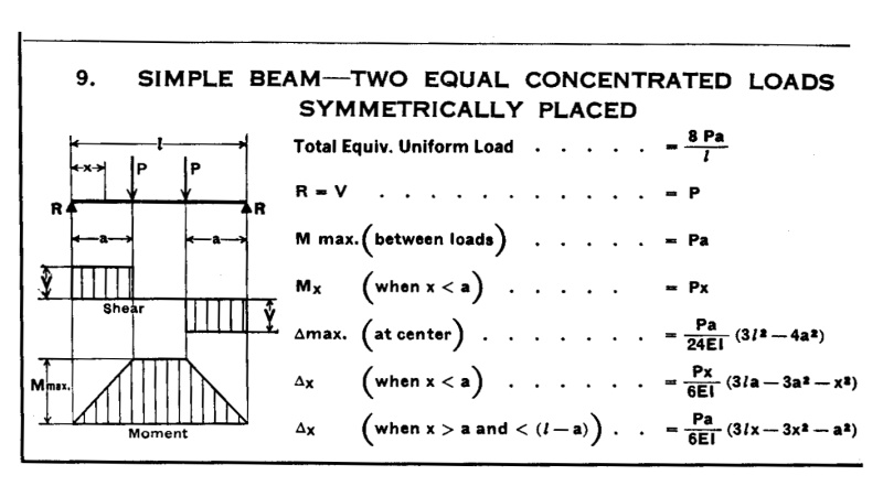
davesen - If you want to avoid the errors in your equations and calculation, there is a direct solution to this problem in the "Beam Diagram and Formulas" section of the AISC Manual of Steel Construction. The illustration below is from Page 2-298 of the 9th Edition.
Just "flip" your sketch upside-down and you have an exact match to this case. Solve for shear and moment. Use Modulus of Elasticity, Moment or Inertia, and Section Modulus for the members you are interested in to determine stresses and deflections.

Beam_Diagram_and_Formula_-_No._9_irhxju.png


[idea]
[r2d2]
 
Status
Not open for further replies.

Part and Inventory Search

Sponsor