Continue to Site

Eng-Tips is the largest engineering community on the Internet

Intelligent Work Forums for Engineering Professionals

  • Congratulations KootK on being selected by the Eng-Tips community for having the most helpful posts in the forums last week. Way to Go!

Beam Tension Flange Restraint (Eurocode)

Status
Not open for further replies.

mattyjb88

Mechanical
Sep 15, 2010
12
Hi All, hoping for a little guidance here.
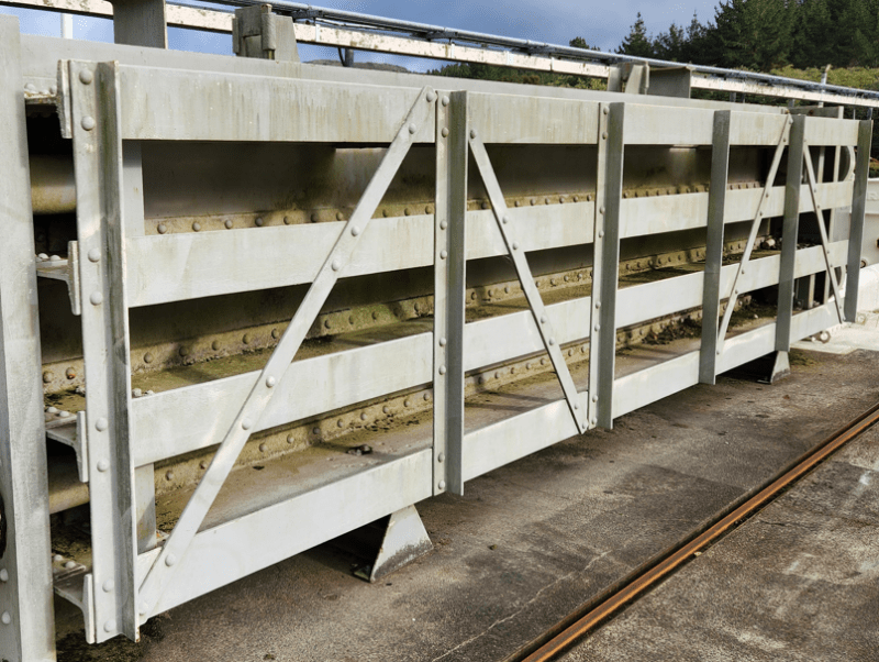
I am assessing a hydraulic gate which essentially comprises several 24"x7-1/2" horizontal I-Beams rivetted (it's old) to a 1/2" steel skin plate. Span is ~7 m, the ends are arranged such that its essentially simply supported. Hydraulic loading is such that the skin plate is in tension. Photo below of one example. The assessment is to Eurocode, which is new for me in my part of the world.

Two questions:
1. The beams have angle placed across the compression flanges, however my understanding is this cannot be used to discount lateral torsional buckling as it is only spanning from beam-to-beam over the compression flanges so does not provide sufficient rigidity. Also it is too far from the plastic hinge (beam centre). Would this read be correct?

2. The 1/2" skin plate will provide lateral restraint to the beam tension flanges (and I assume also some minimal torsional restraint), which provides some limited resistance to lateral torsional buckling. Can this be accounted for in EN 1993-1-1? I note BB.3.3 seems to discuss this, but I struggle to see how it can be applied to a continuous plate restraint.

It is difficult as Eurocode is aimed at buildings, which this clearly is not! However, this is the code we have been asked to use, so, so be it.
Example_yvtwem.png
 
Replies continue below

Recommended for you

That's quite an interesting structure, is the loading imparted from the water on the same side as the photo?

In any case to address your questions:

mattyjb88 said:
1. The beams have angle placed across the compression flanges, however my understanding is this cannot be used to discount lateral torsional buckling as it is only spanning from beam-to-beam over the compression flanges so does not provide sufficient rigidity. Also it is too far from the plastic hinge (beam centre). Would this read be correct?

Personally I would take account of their capacity to resist the LTB effects, you have some additional flat bracing (and possibly anchor points below?) which would form a 'truss' of sorts to restrain the assembly. There is some guidance from the SCI which may be of use on how to determine the reduced beam capacities if susceptible to LTB.


mattyjb88 said:
2. The 1/2" skin plate will provide lateral restraint to the beam tension flanges (and I assume also some minimal torsional restraint), which provides some limited resistance to lateral torsional buckling. Can this be accounted for in EN 1993-1-1? I note BB.3.3 seems to discuss this, but I struggle to see how it can be applied to a continuous plate restraint.

Personally I would discount the restraint effect to the tension flanges, the compression flange generally dictates the buckling of an open section.... Unless the load can be reversed? and therefore the tension and compression flanges can be reversed? Worth bearing this in mind for your checks.
 
Hi MRob909, thanks for your reply.
Yes, the water load is imparted from the same side as the photo - the skinplate and sealing arrangement are both downstream. The load cannot be reversed (unless something very wrong has gone on!).

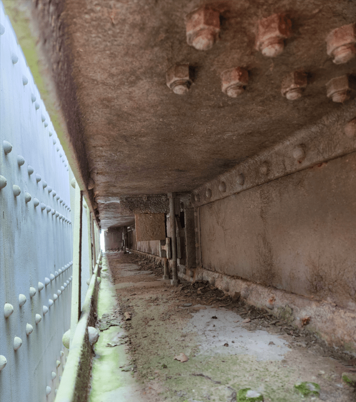
Re the flat and angle bracing, this is all fixed only to the compression flange, there are no gussets, ties, etc, to the tension flange. The below photo shows a view down the inside of the beam structure (the triangular things at the bottom of the stoplog in the photo in the last post are the storage stand it is sitting in.).
Screenshot_2023-09-25_213857_mdv5fo.png


Re resistance to LTB, would the correct understanding be visualized by the below? EA = equal angle.
E.g., the equal angle is helping to prevent rotation of the compression flange.
Screenshot_2023-09-25_214206_rcughr.png

Upon reflection I see this as being of greater assistance that lateral support (given the angle spans the compression flanges beam-to-beam only). Because the angle is relatively light (~3"), it is not immediately obvious that it supplies full restraint. There is little guidance in 1993-1-1 on this, although other codes define 2.5% of the compression flange load (also referenced in 6.3.5.2) but this is not helpful to rotation resistance. Are you aware of a codified method for ascertaining the additional stiffness? If the consequential effect of the angle is full restraint at these points, then the segments between the angle can develop the full section capacity according to LTB calcs. As I understand it, the plastic hinge is "not-rotated" so section 6.3.5 permits this approach.

I see your point about the tension flange contribution. In this case I am considering the section as a built-up section with the allowable width of skinplate contributing to the HR beam section.
 
I'm with MROB909 on this one. I think it's about the vertical truss bracing the foreground flanges.
There's a trick though: the form of the truss assumes that the foreground flanges want to buckle in the downwards (gravity) direction

I don't like the angles as roll beam / torsional bracing. You usually want to engage much more of the beam cross section for that to be effective.
 
Status
Not open for further replies.

Part and Inventory Search

Sponsor