Eng-Tips is the largest engineering community on the Internet

Intelligent Work Forums for Engineering Professionals

  • Congratulations waross on being selected by the Eng-Tips community for having the most helpful posts in the forums last week. Way to Go!

Beam-to-Beam bolted connection 5

Status
Not open for further replies.

SiggiN

Marine/Ocean
Mar 18, 2019
33
NO
Hi all!

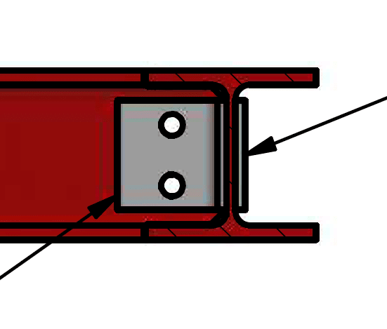
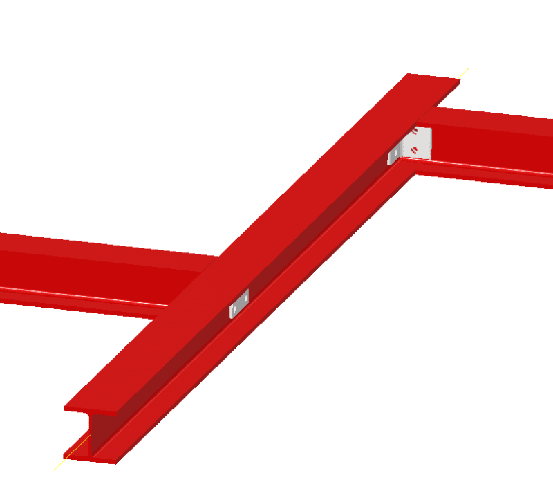
I'm wondering if anyone had some thoughts to the proposed beam-to-beam connection shown below, that consists of

two angles on either side of the web with a support plate on the transverse beam.

I've googled different beam-to-beam connection and did not find this particular, so i'm wondering if it is no good?

My reason for choosing this is becase of the easy installation (no welding):

- HEB 140
- Angle and bolts (calculation pending)
- Load on longitudinal beams approx. 10-13kN/m
- To be used in my new house :)
- assuming bolted connection can transfer moment
- No loads on transverse beam, except loads from connection and end reactions

Thank you!
Bolted_connection_bx42nq.png


Bolted_connection_1_si04qa.png
 
Replies continue below

Recommended for you

You note “assuming bolted connection can transfer moment”. This detail looks reasonable as a pinned connection to transfer shear - not moment. Is this supposed to be a fixed end??
 
There is no moment transfer, this is a typical shear connection.

- No loads on transverse beam, except loads from connection and end reactions

Silly, but If there is no load on the beam, where is the end reaction coming from? You probably mean self weight only?

I am not convinced the plate on the back is doing anything, other than subject the bolts to double shear. But if you have no loads or small loads as said above, that wouldn't be a problem, why add it?

I have no data of what you are trying to do so don't take my word for it. You know your system.

If you are not a structural engineer then hire a competent engineer to do the design for you. Free advice on forums and "Googling" is by no means substitute for consulting services which cost time and money.
 
I’m not convinced that arrangement even gives you double shear in the bolts. The back plate is redundant really.
 
If the connection needs to carry moment (cantilevered?) you need to connect the flanges. For the flange connections you can specify a full depth groove weld without explicitly checking the strength of the weld if the filler metal is stronger than the base metal.

I assume this doesn’t need to be a moment connection though. Are the beams connected at both ends? If so a simple shear connection will do. Look up double angle connections. The plate at the back isn’t needed.

You need to have a competent structural engineer design the beam and connection. It’s likely you have loads in the beam that you aren’t even aware of unless they are interior and decorative only.

I’m not sure where you are located, but in my area you couldn’t get this approved by the building department without a PE stamp anyway.

“Any idiot can build a bridge that stands, but it takes an engineer to build a bridge that barely stands.”
 
Thank you guys!

I will have someone experienced take a look at this, but I did study structural engineering a long time ago (in a galaxy far far away[wink]) so thought it a nice mental exercise (haven't worked as a structural engineering...yet)
Sorry! I could have supplied more information:

- I'm located in norway (Eurocode 3)

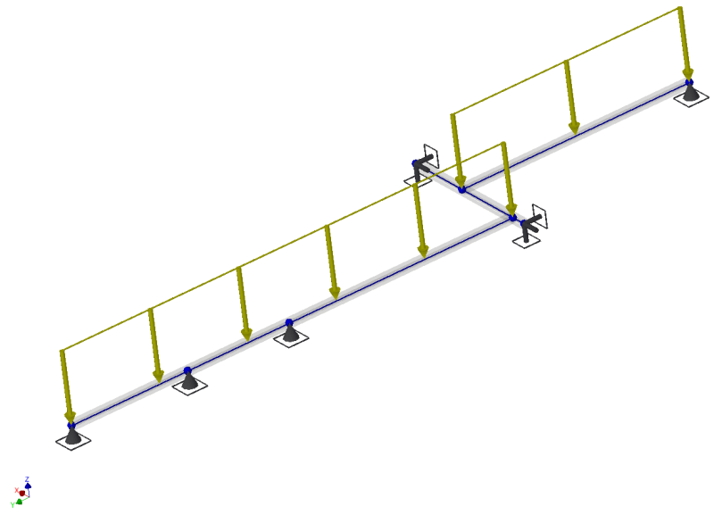
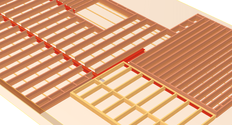
- HEB140 to carry weight of floor (2kN/m^2 * load factor), see picture below

- Maybe i'm overly conservative when assuming moment connection?!
- My reason was to ensure proper bolt size and grade (pending calculation). With the moment acting as a couple
- Calculating bolts based only on shear seemed...too simple

Total_picture_y6hki2.png


Beam_connection_zfg5fl.png
 
SiggiN said:
- Maybe i'm overly conservative when assuming moment connection?!
- My reason was to ensure proper bolt size and grade (pending calculation). With the moment acting as a couple
- Calculating bolts based only on shear seemed...too simple
There is some moment induced in the connection due to eccentricity, this may be what you are referring to.

The connection itself is quite 'flexible' and would allows some rotation hence it is typically treated as a simple pinned connection with no moment transfer from the supported beam.
 
Almost every structural joint will have some moment capacity, but it is usually ignored in the analysis, as the not very meaningful moment can be relieved through the flexibility of the simple shear connection, if the entire structure is stable.
 
As noted above, this is a very standard double cleat connection. Assume pinned ends / no moment at the connection to the supporting beam.

Typically I would assume the 2 bolts between the double cleat and incoming member are subject to a bending moment (due to the end reaction x offset from CL of the supporting beam to bolt CL) and shear (due to the end reaction), and act, if you like, as a continuation of the incoming beam. These will be in double shear for a double cleat.

The 4 bolts between the double cleat and supporting member are subject to single shear (due to the end reaction).

The backing plate does not allow for double shear in the bolts (it's loose usually) and is usually provided to stiffen the supporting beam's web if bolt tension (due to any axial load in the incoming beam for instance) is causing web bending. In some instances the backing plate may be welded to the supporting beam in order to improve bearing length for the bolts, but I don't see that often.
 
Status
Not open for further replies.

Part and Inventory Search

Sponsor

Back
Top