Continue to Site

Eng-Tips is the largest engineering community on the Internet

Intelligent Work Forums for Engineering Professionals

  • Congratulations KootK on being selected by the Eng-Tips community for having the most helpful posts in the forums last week. Way to Go!

Beam to beam connection

Status
Not open for further replies.

PWI94

Structural
Apr 27, 2018
4
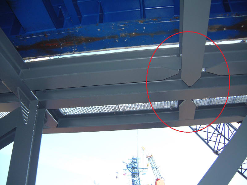
Can anyone explain the following connection;

I-beam to I-beam (same depth and orientated in the same plane) 'Tee' connection - Top flange to top flange welded, web to web welded, intersecting bottom flange sniped and not welded to other flange.

It would seem to me that this is not fully fixed or fully pinned. I'm not sure I see the purpose of this connection.
 
Replies continue below

Recommended for you

welding the top flange and the web together would give some (but probably not much) moment restraint. Even less if tension on the lower flange.

welding both (top and bttm) flanges and the web would give much more moment restraint.

But remember, bending moment on one leg of the Tee will be torsion on the other leg. Even if there is perfect bending continuity this torsional stiffness will limit the bending capacity of the joint.

another day in paradise, or is paradise one day closer ?
 
If I'm picturing it correctly, I don't see the purpose of the connection either.


BA
 
DSCF0061_n70qye.jpg
 
Cool looking connection for sure, maybe engineer was trying to ensure (over done) the top flange of the beam being "t" into in braced for lateral torsional buckling, I wouldn't see the purpose of then welding the webs, but it definitely is a cleaner finish.
 
it looks to me like you've welded both flanges at one end of each piece and at the other end welded just one flange. I cannot see a logic for this.

another day in paradise, or is paradise one day closer ?
 
Another guess is the top flanges are welded to increase the axial capacity of the connection
 
It's possible the connection is designed to carry primarily shear, and the designer wants to limit the stiffness for bending and avoid a fatigue-prone detail. I saw a picture just yesterday of a bridge with a similar connection, except the bottom flange was connected - the bottom flange had a crack all the way across. Presently, the shear capacity is fine, but if the crack propagates into the web, the shear capacity will be reduced.

The tapering they did on the bottom flange is similar to what we use for cover plates, stiffeners, etc. to avoid stress concentrations that could lead to fracture.
 
tapering the flange I get. I don't get fully welding one end and partially welding the other ? welding just the web for shear effectivity I'd understand. I can see that reducing the bending effectivity of the joint increases the flexibility of the joint, reducing secondary bending that can become an issue. Do you think they over-thought it ? Even if it has made (to date) and effective design.

another day in paradise, or is paradise one day closer ?
 
For simple spans, which these appear to be, the top flange connection would be in compression, and therefore not at risk for fatigue cracking. It can be welded to increase lateral stability without concern of fatigue and fracture of the connection.

Maybe it's going to be left exposed, and it's an aesthetic feature...
 
You'll get a bit of fixity (even though the bottom flange appears coped back) because of the web attachment on the other side. If it was just on one side, the girder's web would distort.....and you wouldn't get much fixity. Here you are going to get some (whether you want it or not).

 
Hello
Good question. The primary beam should be the beam over the columns. The beam on the outboard edge makes sense, but the secound beam between on the other side of the primary beam is harder to see a purpose for. Except for some reasons listed above. It looks like a afterthought of some kind. Maybe something to do with the type loading above. Or a way to distribute moments or loads away form the circled joint. As this beam acts more like a cantilevered beam (to some extent).
 
This looks like an industrial install, so it might have something to do with unusual loading conditions.

I don't really see this here, but I'd expect to see fixity on one end of a beam and no fixity on the other if it was acting as a restraint for torsional loading on the beam that the fixed end is connected to. You also might see a situation where you weld the top flange but not the bottom if you have an out of plane top flange load but don't want to (or don't need to) develop strong axis full fixity. You also might have some sort of axial loading condition where you don't need full fixity or where it's been concentrated in the top part of the section due to loading conditions.

There's also a chance that it's some detailers way of justifying that the top flange is laterally supported.

Or maybe they just wanted a flush top surface with no gaps for some sort of serviceability or perceived constructability reason that may or may not be realistic.

 
Status
Not open for further replies.

Part and Inventory Search

Sponsor