Eng-Tips is the largest engineering community on the Internet

Intelligent Work Forums for Engineering Professionals

  • Congratulations waross on being selected by the Eng-Tips community for having the most helpful posts in the forums last week. Way to Go!

Beam to column connection with eccentricity 4

Status
Not open for further replies.

Mike1998

Structural
Oct 5, 2018
9
NL
Hi all,

I have a question regarding a beam to column (hinged) connection (see the attached file).

The beam transmits a reaction F to the flange of the column with an eccentricity e from the centerline of the column. Should I check the column with a bending moment M = F*e?

Thank you in advance.
 
 https://files.engineering.com/getfile.aspx?folder=bf046b00-f4b7-481d-9bdc-ab6cd2821e05&file=column.jpg
Replies continue below

Recommended for you

IDS said:
Not saying you are wrong, but what is the justification?

Right after the word "justification" in my previous post, I listed the three justifications that I'm most familiar with. And that's the lion's share of what I've got in my bag of tricks. Note that those things reflect less my own personal opinions than they do the opinions of others practicing in my market.

When I choose a low axial utilization ratio over a detailed look at eccentricities, my own "justification" is really:

1) I simply do not perceive that the world has a meaningful gravity post problem. One has to pick their battles as a structural engineer and this isn't the one for me. I feel that structural designs, and structural drawings, often have more serious deficiencies and that more attention in those areas represents a better return on investment.

2) As a structural engineer, I view myself as a moderately skilled, rough proportioned of things. As an industry, I feel that we tend to get too obsessed about accuracy in a space where any rational person must acknowledge that little meaningful accuracy is available to be had.

Now for a fun anecdote.

One of my first assignments as a newly minted graduate engineer was the design of a bunch of steel columns in a one story joist & beam building. My boss was an interesting character in that he was a very practical engineer but would never, ever utter the phrase "overthinking" to me. He'd adjust schedules and hemorrhage fees at will if that's what it took to buy me the space to do whatever I felt needed to be done. I think that he mostly just kept me around for company (two man dept) rather than production.

What I felt needed to be done was to check all of the "posts" for moments at the top and bottom arising from eccentricities in the two to four incoming framing members which may be pattern loaded. I had oodles of cases to check, oodles of things to consider, and built myself a giant spreadsheet to help. It took me the better part of two days and I almost choked on the assignment altogether. At the end of it, I asked my boss how he typically handled this stuff. I was ready to give up engineering and take up accountancy.

He said that, for a gravity post of a typical cross section and with typical shear connections, he ignored the eccentricity but kept the axial utilization under 80%. I looked at my numbers, realized that would have worked comfortably in all cases, and agreed that was a rational approach. 90 seconds per column design without the aid of software. More time to add missing details to the drawing set and wonder if the entire building might rack over sideways.
 
Lomarandil said:
If the connection (and local effects on the column, which I include in connection design) are designed to transmit the forces and moments to the column centerline, haven't I replaced my physical beam with an 'effective beam' spanning from node to node? In this case, what is left for design of the column?

How would that preclude moments developing within the column? I would argue that it doesn't and that you'd still have this to contend with in the macro-design of the column:

1) Combined axial and flexural stresses throughout the entire length of the column and;

2) Exacerbated P-baby-delta moments within the column associated with the flex induced in the column. This leads to a lower buckling capacity.

The trouble with structures is that their lousy listeners. Trying to tell them that their concentric doesn't necessarily make it so.
 
I like your story Kootk. And it seems that your approach aligns more with mine than Agent666. I also think Agent666's point is pertinent, if you haven't asked the question or explored the results people might be quite in the dark about the degree that eccentricity affects their demand/capacity calculation.

To that end I checked some UBs columns in a model I have with weak minor axis. The difference was less than I expected, 2% difference at critical case and 12% at highest axial load (not critical case). All these UB columns have a capacity/demand ratio of over 2. Which seems excessive but the were sized to match stocky UC columns beneath. I could have spliced it a floor below but then the capacity/demand ratio would have been sailing much closer to the wind.

Anyway. I probably have not much further to add. This thread made me explore something a little deeper, which is why I read these threads. [thumbsup]
 
I like the NZ method too. It seems to be the most rational out there in terms of clear guidance. This is one of those situations where I actually wish that North American codes would just prescribe what should be done. That way:

1) We'd all be doing the same thing.

2) Software would adapt.

3) The material costs would surely be inconsequential.

4) We'd free up our collective intellects for more worthy considerations.

I'm usually in the minority in that most engineers disdain heavy handed codes and would prefer to retain their autonomy for stuff like this. Not this cowboy though. I feel that codes do me a nifty service when they force my competitors to design consistently and safely on routine items. I'm happy to flex my creative muscles in concept design etc.
 
Kootk said:
I like the NZ method too. It seems to be the most rational out there in terms of clear guidance.
As Agent666 surmised, the Australian code reads the same. Though in my experience, Australian engineers ignore this prescription a fair bit. Either out of laziness, ignorance or confidence in their own judgment. Of course if you start ignoring code items you are going down a precarious path.

Australian codes and NZ codes are quite similar and are often shared or jointly produced. Though I do start to wonder if NZ is surpassing AU codes in quality. Their seismic requirements have driven the need for for comprehensive codes in some areas and an entirely separate code for seismic loads.


Most of us have likely seen dozens or hundreds or poorly or otherwise underdesigned structures. The biggest savior is likely that most structures rarely see ultimate loads. I've designed quite a few elevated bulk storage structures which have very high load in a relatively small space combined with a moment lateral restraint system. This means that the columns end up working extremely hard when axial loads combine with lateral loads. Yet I've seen similar structures built by others which have about half the capacity. I have little confidence they would stay upright with ultimate wind or seismic loads occur.
 
Kootk said:
KootK (Structural) 13 Apr 21 15:15


Quote (Lomarandil)

If the connection (and local effects on the column, which I include in connection design) are designed to transmit the forces and moments to the column centerline, haven't I replaced my physical beam with an 'effective beam' spanning from node to node? In this case, what is left for design of the column?

How would that preclude moments developing within the column? I would argue that it doesn't and that you'd still have this to contend with in the macro-design of the column:

1) Combined axial and flexural stresses throughout the entire length of the column and;

2) Exacerbated P-baby-delta moments within the column associated with the flex induced in the column. This leads to a lower buckling capacity.

The trouble with structures is that their lousy listeners. Trying to tell them that their concentric doesn't necessarily make it so.

On 1, I don't think this matters, as long as you have defined a load with a flexural compressive stress state that column passes. Basically the entirety of connection design, and steel design in general already works like this.

On 2, I think if the connection has some moment capacity, then it has enough restraint to reduce the P- small delta effects. And this would be true throughout the structure - all connections modelled as pinned have some capacity to reduce flexure in the column. So from a global stability perspective, you are already modelling a safe lower bound of structure stiffness.

My approach is, in order of preference
a- for columns with members framing in from all directions, or part of a large braced frame/moment frame where I'm confident there is a robust load path for the moment - keep utilization low enough in the column I'm happy. Still modelling the beams full length as well.
b- model the beams full length, make sure that the connections have some nominal moment capacity, and call it ok.
c- model the eccentricity, mostly in cases where there is a true post condition and I'm concerned about lateral stability, or if there some potential for weak axis moment in the column.
 
canwest said:
On 1, I don't think this matters, as long as you have defined a load with a flexural compressive stress state that column passes. Basically the entirety of connection design, and steel design in general already works like this.

I disagree strongly except for how connection design is envisioned to work. I feel that, if the column will see flexural stress in addition to axial, that will affect the column design as parts of the cross section will yield earlier, there will be an LTB demand this wouldn't exist otherwise, and Baby-P-Delta buckling tendencies will be exacerbated for axis coincident with moment. In my mind, having a place to redistribute moments to does not prevent moments from developing. One might cap the moment at the development of a stable flexural hinge somewhere in the system but, as far as I know, nobody is designing gravity posts that way. And I would expect that to yield prohibitively inefficient column designs.

canwest said:
On 2, I think if the connection has some moment capacity, then it has enough restraint to reduce the P- small delta effects. And this would be true throughout the structure - all connections modelled as pinned have some capacity to reduce flexure in the column. So from a global stability perspective, you are already modelling a safe lower bound of structure stiffness.

I made basically the same point in my first post. But, then, I also made the point that this is a benefit that is:

a) difficult to quantify and;
b) is not being quantified by designers as far I know.

So I think that sketchiness remains in that you're trying to offset a tax (eccentricity) with an undefined credit (connection fixity).

canwesteng said:
Still modelling the beams full length as well.

lomarandil said:
...haven't I replaced my physical beam with an 'effective beam' spanning from node to node?

Obviously I can't read you guys' minds. I'm going to try though. These arguments sound to me like analogs to a common concrete design strategy: If I design my concrete thing to span to the center of the supports, I can ignore the torsion in the supporting girder.

That argument is substantially valid. However, when we do that, we also provide at least compatibility torsion reinforcement in the supporting member. And there's no analog to that in the case of steel post design. In steel post design, we are not taking any steps to ensure that the member as a whole has redistribution capacity.
 
Concrete is an entirely different ball game, especially in that example, since you can be well underreinforced for torsion, and have sudden brittle failure of the member. Specific to the LTB case - as LTB develops, that load path will become softer and the moment will re distribute to the beam, assuming it is proportioned for it. Now for a true gravity post, sure you'd add some eccentricity to account for instability effects. For a column where the beams framing into it form part of diaphragm, I don't see an issue having the connection transfer small moments so that the reaction occurs at column CL.
 
canwesteng said:
Specific to the LTB case - as LTB develops, that load path will become softer and the moment will re distribute to the beam, assuming it is proportioned for it.

So you're actually willing to allow lateral torsional buckling to be a deliberate part of your redistribution mechanism?

canwesteng said:
Now for a true gravity post, sure you'd add some eccentricity to account for instability effects.

So you don't design your posts for all of the eccentricity but, rather, some of the eccentricity? How do you decide how much?

canwesteng said:
For a column where the beams framing into it form part of diaphragm, I don't see an issue having the connection transfer small moments so that the reaction occurs at column CL.

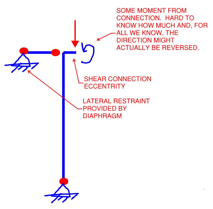
How do you see the diaphragm altering the situation? I see it as shown below which would have no impact on the stability design of a typical gravity column.

Moreover, how is it that you have any certainty that the reaction is coaxed into occurring at the column centerline? Your providing the capacity for a nominal moment connection at the joint is no guarantee that the structure will choose to exploit that 100%. You know, the stiffness thing.

C01_i7hawc.jpg
 
I concur with Kootk and am I am thoroughly confused by anybody who is trying to handwave away eccentric effects by saying (if I understand it correctly) that they have accounted for it in their connection design.

Eccentricity matters, how much detrimental effect it can hap depends on the circumstance so start ignoring it at your own risk. While I've discussed my rationale for not specifically allowing for it in some circumstances, I'm in no way arguing that it doesn't put extra demand on my members that isn't specifically allowed for.
 
Kootk said:
Quote (canwesteng)

Specific to the LTB case - as LTB develops, that load path will become softer and the moment will re distribute to the beam, assuming it is proportioned for it.

So you're actually willing to allow lateral torsional buckling to be a deliberate part of your redistribution mechanism?


Quote (canwesteng)

Now for a true gravity post, sure you'd add some eccentricity to account for instability effects.

So you don't design your posts for all of the eccentricity but, rather, some of the eccentricity? How do you decide how much?


Quote (canwesteng)

For a column where the beams framing into it form part of diaphragm, I don't see an issue having the connection transfer small moments so that the reaction occurs at column CL.

How do you see the diaphragm altering the situation? I see it as shown below which would have no impact on the stability design of a typical gravity column.

Moreover, how is it that you have any certainty that the reaction is coaxed into occurring at the column centerline? Your providing the capacity for a nominal moment connection at the joint is no guarantee that the structure will choose to exploit that 100%. You know, the stiffness thing.

Well, I don't think LTB occurs - before that there is certainly going to be a loss of stiffness. In any cases, where we have clean, ductile failure modes seems like an odd place to trying and button down the exact behavior - especially when column base plate are essentially end plate moment connections that we model as pins, and often concrete breakout would govern their failure. Taken further, do we need to look at the fixity in gusset plates adding moments to braces? There are probably a limitless number of examples where we design a ductile material by providing a lower bound solution, and rely on the material to behave as we've decided. Now in situations where this ductility has been overstated, certainly some failures have occurred.

Maybe an error in wording - I'd add all the eccentricity to it. Although we also have vertical loads on both sides of the column with counteracting moments, so in order to see a moment on the column you need to have an unbalanced load reducing column capacity anyway.

In the case of the diaphragm, the P-big delta effects from this eccentricity don't occur, only the P-small delta effects, which if you're happy to ignore the eccentricity then as a result you're happy to ignore these as well.
 
Thanks for the explanation canwesteng. That said, I plan to flip flop and agree with Lomarandil's (and probably yours) approach, at least for a wide range of practical gravity post cross sections. More to follow.
 
KootK said:
That said, I plan to flip flop and agree with Lomarandil's (and probably yours) approach
Damn you does that mean that since I agreed with you earlier I need to flip flop too? :p

For single story columns the eccentric pinned connection vs the stiffer moment connection almost balances itself out due to the effects on effective length. This was demonstrated in a thread here on a beam to column cap plate connection discussion.

For multistory type applications where there is significant axial load above the eccentric connection I believe you could see quite significant real effects of eccentric loads on columns particularly narrow flanged columns. I haven't demonstrated this to myself by Agent666 seems to have experience here. EDIT: I ran a quick check. It really isn't hard to come up with eccentricities where your capacity/demand ratio halves. Mind you the 100mm requirement of NZ and AU codes is pretty brutal on light columns, but even a more realistic 50mm is still rough on the column's minor axis.
 
KootK said:
How would that preclude moments developing within the column? I would argue that it doesn't and that you'd still have this to contend with in the macro-design of the column:

You're right, I didn't describe what is going on inside my head very well. Still working on a better explanation.

----
just call me Lo.
 
Although we also have vertical loads on both sides of the column with counteracting moments, so in order to see a moment on the column you need to have an unbalanced load reducing column capacity anyway.

Yes, very easy to get unbalanced moments when you consider for example 0.9G on a beam one side and 1.2G + 1.5Q on the other beam opposite.

This is based on net stabilising and destabilising effects and how they impact on the worst-case scenario for the column, most codes have some similar requirement. This is the requirement required to be considered in AU & NZ codes, least my interpretation of it. Assume 1.2G+1.5Q load from above, load below is load above +0.9G from one beam, +1.2G+1.5Q from other beam. Work out worst case out of balance load based on highest beam reaction minus the lowest, apply the 100mm eccentricity from face of column. Check column for axial load and the bending from unbalanced eccentricity moment. This is usually more critical than taking the net unbalanced moment generated from full load on both beams (even if the axial load is slightly higher if you were to do this). Check all columns top down in this manner.

As well as above whilst we are on column design, if in a seismic region check the actions resulting from deformation compatibility in addition to eccentric moments, obviously if these columns are attracting axial loads form the seismic system this case can govern over and above the gravity ultimate limit state cases.

 
Agent666 is busy putting the fear of god under me and making me want to go check everything I've ever designed and comprehensively include eccentric effects of the connections. [rednose]

(I'm actually fairly comfortable. I had a very early learning experience with columns bending like a bananas on a jobsite. It has made me somewhat wary of excessive eccentricities OR inadvertent moment transfer to columns. At the time I was working a fabricator not the engineering firm responsible.

Still I value your input Agent666 because you seem to be the loudest voice saying eccentricity MATTERS!
)
 
Just to clarify one thing I said in my last post, the 0.9G I consider is only the permanent dead load, i.e. no superimposed dead load or any dead load than cannot be removed is included. For the NZ or Australian folks following along, this is covered in the commentary CL C4.2.2 of AS/NZS1170.0.

So, for a simply supported beam system, just self-weight of the beam and structural slab would be included on side, and the full ULS loading from the other side. If you consider real world ULS loading, it's more likely to occur on a single beam, rather than over the entire floor system at once. So you're more likely to see the out of balance moment if you consider one side being overloaded in practice.

 
Totally agree on that last point Agent -- I teach the same thing to my engineers. Personally, I've borrowed the term "Dead Collateral" load from the bridge world.

----
just call me Lo.
 
As far as I am concerned it has always been a bit fuzzy the line between long term live loads and dead loads.

I deal with bulk material handling and storage. So sometimes the main structural load is a fairly well known volume of a well defined material of known maximum density. Calling it a live load with a 1.5 factor ontop of an already conservative maximum density start excessively conservative. AS3774 has a load factor of 1.25 which is a bit more sensible, but few other structural engineers know what I'm talking about if I refer to that code. That said calling it a dead load also isn't suitable because for any wind calc you really can't afford to treat it as a dead load or empty storage bins would fly away in a stiff breeze.

I mostly end up using a 1.5 live load factor which might be excessive but its nice to keep plenty of margin up your sleeve, especially since you do know that the structure will be regularly filled with full live load weight.
 
Status
Not open for further replies.

Part and Inventory Search

Sponsor

Back
Top