Navigation
Install the app
How to install the app on iOS
Follow along with the video below to see how to install our site as a web app on your home screen.
Note: This feature may not be available in some browsers.
More options
You are using an out of date browser. It may not display this or other websites correctly.
You should upgrade or use an alternative browser.
You should upgrade or use an alternative browser.
beam to column - steel connection 9
- Thread starter mats12
- Start date
- Status
- Not open for further replies.
-
1
- #2
Short answer: NO.
Longer answer:
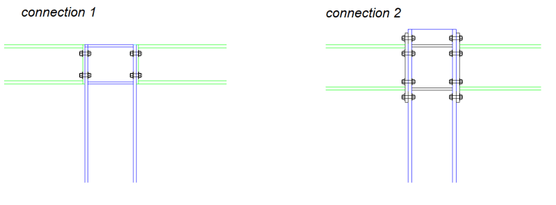
You will struggle to get that connection either stiff enough or strong enough for a suitable moment connection. Have a look and the various resources regarding rigid and semi-rigid connections. The connection on the left I would describer as semi rigid if the plate was thick. I'd normally model it as pinned unless pinned was less conservative than rigid.
Longer answer:
You will struggle to get that connection either stiff enough or strong enough for a suitable moment connection. Have a look and the various resources regarding rigid and semi-rigid connections. The connection on the left I would describer as semi rigid if the plate was thick. I'd normally model it as pinned unless pinned was less conservative than rigid.
- Thread starter
- #4
That's right. The four bolt connection can certainly transmit moment. just on the order of less than half as strongly and half as stiffly as the eight bolt version. Developing the flexural capacity of the beam with the four bolt connection would be tough. But, then, that's not always necessary.
-
4
- #6
It has moment capacity if the connection is designed appropriately. Obviously a deeper beam will allow for more moment. Agree that developing that connection for the beam strength would be difficult for anything but the smallest of beams.
AISC DG 16 has a way to design this connection for moment as well.
Go Bucks!
AISC DG 16 has a way to design this connection for moment as well.
Go Bucks!
canwesteng
Structural
Agree with straub. Both are moment connections and both will had similar stiffness, until the end plate yields.
JoshPlumSE
Structural
I second what Straub said. I'll also point out that connections like he shows from the AISC design guide would be considered "partially restrained" moment connections. Whereas, connection 2 (form the OP) would be considered a "fully fixed" moment connection.
The difference being an AISC classification related to rotational stiffness... alluded to by human99 and KootK.
The difference being an AISC classification related to rotational stiffness... alluded to by human99 and KootK.
As Straub notes... I have SMath programs for this configuration, and is good for small and medium moments. A325 bolts can develop a fair tensile force.
Rather than think climate change and the corona virus as science, think of it as the wrath of God. Do you feel any better?
-Dik
Rather than think climate change and the corona virus as science, think of it as the wrath of God. Do you feel any better?
-Dik
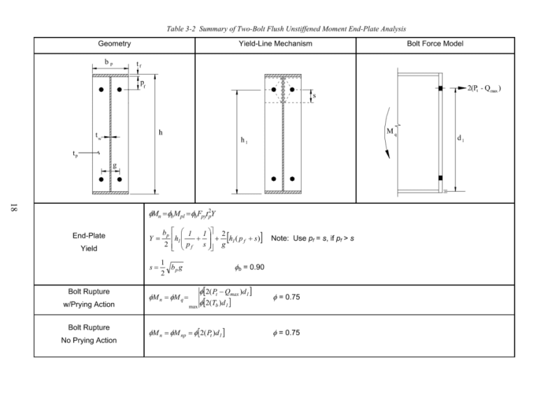
The connection on the left is a flush moment end plate as some have mentioned. If the plate is thick enough, it will behave as a fully restrained moment connection. In Design Guide 16, Equation 2-7 is used to compute the required thickness of the plate. It has a gamma_r factor that is used to make sure the plate is thick enough. For flush, gamma_r = 1.25. For extended, it's just 1.0.
canwesteng
Structural
I think the right sketch would be a four bolt unstiffened connection, which is still classified as partial moment restraint. To be full restraint you need 8 bolts for the tension flange in a 1/3 configuration, or a stiffener.
canwesteng said:...both will had similar stiffness, until the end plate yields.
I disagree with that. Even within the elastic range, I see the stiffness as a function of:
a) The number of bolts stretching.
b) The number of plate elements flexing.
Those numbers for the eight bolt connection would be almost double what they would be for the four bolt connection.
I played around with these in IdeaStatica once. There was no configuration or plate thickness that achieved full fixity of connection 1 based on the CBFEM of that program, at least not with the design loading. I was able to back the loading off and get it to register as fully restrained, but it was an impractically small load. It resisted moment, for sure, but it rotated more than a typical analysis would allow. I was trying to get a beam splice to work in a wood framed structure with no room for the extended end plates. My solution was eventually a really thick plate with a flush end plate on the top and an extended end plate on the bottom. I was able to get sufficient stiffness out of it to the job that way.
JoshPlumSE
Structural
canwesteng said:I think the right sketch would be a four bolt unstiffened connection, which is still classified as partial moment restraint. To be full restraint you need 8 bolts for the tension flange in a 1/3 configuration, or a stiffener.
I'm specifically referring to the AISC designations. Per AISC 15th edition figure 12-1 FR moment connection behavior, connection 2 is shown as one of the examples. Not quite as rigid as a welded flange. But, pretty close.
For Connection 1, it's the AISC design guide (I believe) that recommends that it be classified as a partially restrained moment connection.
-
1
- #17
canwesteng
Structural
Josh -
I see, I was referring to the AISC design guide, it calls both connections above partially restrained.
Kootk -
If the bolts are pre-tensioned as they should be, I don't think there is much bolt stretch until ultimate loads. Which leaves the plate itself, but extended end plate is going to be less stiff than the portion between the flanges (substantially so at the scale sketched above).
canwesteng said:If the bolts are pre-tensioned as they should be, I don't think there is much bolt stretch until ultimate loads. Which leaves the plate itself, but extended end plate is going to be less stiff than the portion between the flanges (substantially so at the scale sketched above).
I'll concede both of those points. Thanks for raising them.
Wow that escalated quickly!
Also I feel I should have stuck with my even longer answer in my original reply that if you have the plate thick enough with suitably strong and tensioned bolts then you could achieve something that approaches a rigid connection.
If I have time I might even dig into this more using desktop models to model the flexibility and compare it to any real world tests that have been done.
**Like I alluded to in my first post. If I have a critical connection in the form of the left type connection I would model it as pinned but I'll check the rigid behaviour as well ensuring it isn't putting too much moment in a place that I don't want it. I've encountered this situation often when placing continuous beams across an A-Frame. Tall A-Frames (25m) can be somewhat susceptible to moment as the effective length of the column is full height in one direction.
Also I feel I should have stuck with my even longer answer in my original reply that if you have the plate thick enough with suitably strong and tensioned bolts then you could achieve something that approaches a rigid connection.
Yes, but you have a significantly lower moment arm so higher forces AND in this drawing a thinner plate. On visual inspection which is all we have here there is no way I'd call the one on the left a moment connection.canwesteng said:Which leaves the plate itself, but extended end plate is going to be less stiff than the portion between the flanges (substantially so at the scale sketched above).
If I have time I might even dig into this more using desktop models to model the flexibility and compare it to any real world tests that have been done.
**Like I alluded to in my first post. If I have a critical connection in the form of the left type connection I would model it as pinned but I'll check the rigid behaviour as well ensuring it isn't putting too much moment in a place that I don't want it. I've encountered this situation often when placing continuous beams across an A-Frame. Tall A-Frames (25m) can be somewhat susceptible to moment as the effective length of the column is full height in one direction.
canwesteng
Structural
True, I had missed the thinner plat on the flush end plate. The moment arm argument is more an argument that the connection on the right has more capacity - but if the connection is properly designed for the load, they could both be moment connections.
- Status
- Not open for further replies.
Similar threads
- Replies
- 0
- Views
- 7
- Locked
- Question
- Replies
- 2
- Views
- 11
- Locked
- Question
- Replies
- 17
- Views
- 18
- Locked
- Question
- Replies
- 6
- Views
- 8
- Question
- Replies
- 10
- Views
- 13