Navigation
Install the app
How to install the app on iOS
Follow along with the video below to see how to install our site as a web app on your home screen.
Note: This feature may not be available in some browsers.
More options
Style variation
-
Congratulations TugboatEng on being selected by the Eng-Tips community for having the most helpful posts in the forums last week. Way to Go!
You are using an out of date browser. It may not display this or other websites correctly.
You should upgrade or use an alternative browser.
You should upgrade or use an alternative browser.
beam to column - steel connection 9
- Thread starter mats12
- Start date
- Status
- Not open for further replies.
Asking if a connection is a "moment connection" could have two different meanings:
[ol 1]
[li]Does the connection have flexural capacity?[/li]
[li]Should the connection be modeled as a rigid connection?[/li]
[/ol]
Since OP mentioned that they had seen the connection used for "cantilever parts of structure" I think their question has the first meaning. In that case, I think the answer is that it can certainly transmit moment. You can treat the connection as fixed to calculate the moment in the connection and the deflection of the cantilever. Then you would calculate the additional rotation caused from the connection itself not being rigid (plate bending, bolt rotation, etc). Finally you would multiply this extra rotation by the length of the cantilever to find the rigid body rotation caused by the connection rotation. You could design the connection to resist the moment using the equations posted by straub46.
The second question may be asked if there was a beam supported at each end by this connection. In that case, the question is a function of the stiffness of the connection as well as the cross sectional stiffness, length, and loading of the beam.
canwesteng said:True, I had missed the thinner plat on the flush end plate. The moment arm argument is more an argument that the connection on the right has more capacity - but if the connection is properly designed for the load, they could both be moment connections.
The moment affects stiffness too as higher loads means more deformation and more rotation. It doesn't take much rotation for a connection that is assumed to be rigid, to be not very rigid at all when considering a beam with 2 fixed ends. If connection isn't rigid enough you could readily end up with the beam design being unconservative even if the connection is strong enough.
Though as chris3eb correctly when you dig deeper there are really two questions being asked.
I don't often design them as rigid fixed connections rather as connections that have a factored shear and moment that must be developed. This can include cantilevered members, like attaching a pipe rack to the exterior of an industrial building... with fabreeka and sheet material to prevent cold and moisture transfer.
Rather than think climate change and the corona virus as science, think of it as the wrath of God. Do you feel any better?
-Dik
Rather than think climate change and the corona virus as science, think of it as the wrath of God. Do you feel any better?
-Dik
HTURKAK
Structural
- Jul 22, 2017
- 3,358
MR. mats12 (Geotechnical)(OP),
I looked to your internet country domain (SI) ..
In this case better to look to the following doc. to get the concept for moment connection complying with EC-3
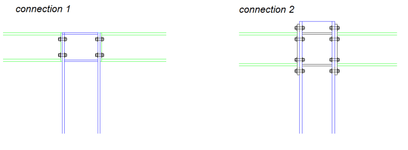
In case of top storey , the use of continuous beam over the column with cap plt. could be better option than ( CONN.1)
I looked to your internet country domain (SI) ..
In this case better to look to the following doc. to get the concept for moment connection complying with EC-3
In case of top storey , the use of continuous beam over the column with cap plt. could be better option than ( CONN.1)
-
2
- #26
canwesteng
Structural
Not sure how true to the test specimens are, but the flush end plate is missing column stiffeners...
milkshakelake
Structural
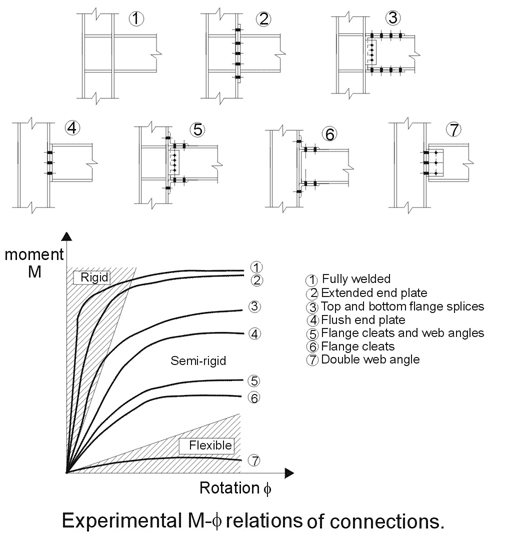
This is honestly a shocker, I would've expected 5 and 6 to beat 4 by a wide margin. Thanks for the table Veer!
I have a feeling some of the surprise here comes down to regional differences in the standard ways of doing connections thus people assuming that they are suitable.milkshakelake said:This is honestly a shocker, I would've expected 5 and 6 to beat 4 by a wide margin. Thanks for the table Veer!
There is very little likelihood that connections 5 & 6 would ever be considered moment connections where I work. I wouldn't say engineers are more knowledgeable around here, the reason is that angle cleats are mostly not used and if you called up a moment connection like that you'd get questioned heavily.
Conversely, we use bolted fin plates around here as 'pinned' connections. They are less close to being an idealise pin than a angle cleat.
(Likewise the industry body here doesn't have any guidelines for flush moment end plates. So generally flush plates are not considered a suitable design for a moment end plate. Despite as pointed out if you have a thick enough plate you can likely achieve enough rigidity and possibly enough strength.)
milkshakelake
Structural
Yes, some people use the angles as semi-rigid connections around here. I've heard of it being used as a quick fix solution to lateral problems in existing structures, not an initial design. 3 is used pretty much universally in my region for new steel.
I thought that the ~1.5x larger moment arm would have made a big difference. But thinking about the flexibility like dik mentioned, I could unfold the angle to a long plate with bolts at the far end, which wouldn't be rigid at all.
I thought that the ~1.5x larger moment arm would have made a big difference. But thinking about the flexibility like dik mentioned, I could unfold the angle to a long plate with bolts at the far end, which wouldn't be rigid at all.
-
1
- #37
Hello @Kootk, Below are some net sources that the info. was found from
Thanks in advance!!
Thanks in advance!!
- Status
- Not open for further replies.
Similar threads
- Question
- Replies
- 6
- Views
- 7K
- Locked
- Question
- Replies
- 5
- Views
- 3K
- Replies
- 28
- Views
- 4K
- Locked
- Question
- Replies
- 9
- Views
- 3K
- Question
- Replies
- 7
- Views
- 4K


