Eng-Tips is the largest engineering community on the Internet

Intelligent Work Forums for Engineering Professionals

  • Congratulations waross on being selected by the Eng-Tips community for having the most helpful posts in the forums last week. Way to Go!

Beam to support impact load. 3

Status
Not open for further replies.

CSFlanagan

Structural
Mar 17, 2006
23
US
I'm designing a steel frame to protect employees walking under an overhead crane that carries a basket of steel. The frame I am designing is like a heavy duty canopy. It is 15' x 60' long and 13'-6" tall. It is not supporting any other loads, and will only see a load if the basket being carried by the crane above falls.
Maximum beam span is 30 feet. The basket carried by the crane weighs 5,000 pounds fully loaded. The bottom of the basket is only 12 inches above the top of the "canopy", so height of fall is only 1 foot.
My gut tells me to use an impact factor of 2.0, and design for a 10 kip load applied anywhere on the support frame. However, I'd like to have something more scientific to include in my calculations.
I've tried using assumptions of time for deceleration to determine the load. Using this method, the stiffer the beam that is selected the higher the force that gets applied. Essentially, an infinitely stiff beam creates an infinite force. Intuitively this cannot be correct, so I must be doing something wrong.
I've seen other posts, and they have asked for specifics. I hope I have provided enough information for a calculation.
What are your thoughts?
 
 https://files.engineering.com/getfile.aspx?folder=fab741ac-42d3-4db1-a44e-430cff7f2e38&file=SectionView.pdf
Replies continue below

Recommended for you

This reminds me of a rockfall/boulder protection structure. Some rockfall fences use ductile nets to absorb the kinetic energy of the boulder. Rigid, tunnel-like structures sometimes use a sand cushion layer to absorb the kinetic energy of the boulder impact and spread the load to the beams. Maybe similar principles could be applied to this structure.
 

That's the 800 pound gorilla in the room. These types of designs are always tricky. For example, in NYC, the canopy, which we would call a sidewalk shed, is designed for 300 psf live load for buildings over 100' and 150 psf for buildings under 100'. Where these values came from no one knows; do they really work? No one knows.


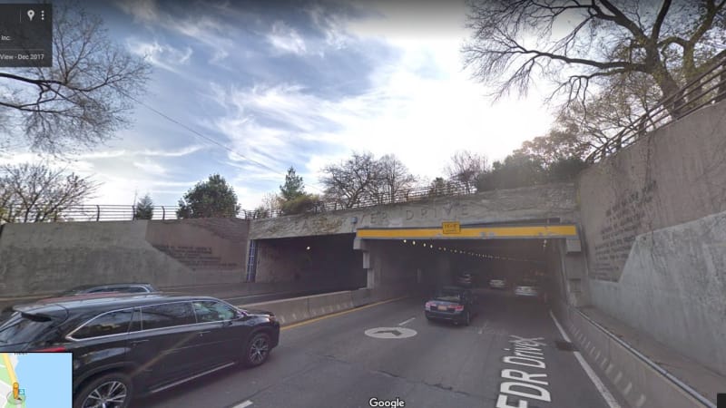
This picture shows a collision beam on the FDR Drive in Manhattan, near East 90th Street. It's intended to rip the top off of trucks, which aren't permitted on that road. The design load is a 54K vehicle travelling at 60 mph but I don't see how it can work because it can barely hold up it's on weight. (I had to design one for another location and the client gave me the plans as an example). Meanwhile, it must work because it's been hit and it's still standing. I think this one may have been designed using LS-Dyna, which is a finite element progam for collision and impact loads.

x_jcywaw.jpg
 
The primary load hitting that collision beam is made of flimsy aluminum. On the 11foot8.com site are a number of such collisions and the vehicles that stop take several feet to stop from 30mph.

I have seen a different load - an approximately 8 foot diameter 5/8ths wall tube 40 feet long going 60+mph. It hit a bridge I-beam - about 3 feet deep, 3/4 inch bottom flange (dimensions via eye-ball). It bent the web and flange to where a 20 foot section was twisted about 45 degrees. I estimate that it stopped the tube and the semi it was attached to in under 3 feet from the 60+mph.

The cause was the highway department's fault - while part of the construction was to increase the clearance at that overpass by lowering the traffic lanes, they had not lowered all the lanes yet, but allowed the overpass bridge to be rebuilt two lanes wider. Since the highway is sloping uphill this meant that the increased width decreased the clearance on one side. The tube hit the farthest beam after clearing (I think) 5 others. The trucker would have depended on the existing posted heights which had not been changed at the time of the collision.

The bridge was designed so the beams were buried in concrete at the ends, so the repair was effected using torches. I don't know what else they used, but the paint was burned from significant sections of that I-beam.

I think the driver lived; there was no mention of the crash in any news, so I expect the state DOT must have paid everyone a significant amount of money to keep quiet on top of compensating the injuries.
 
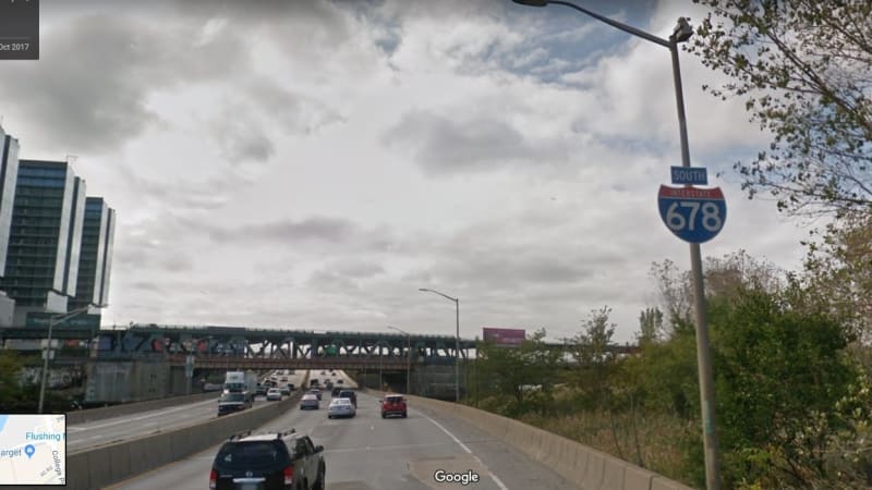
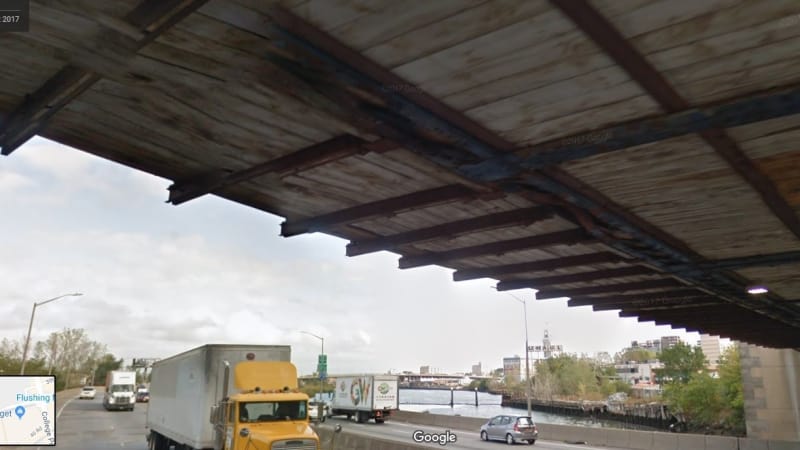
I look at 11Ft8.com from time to time; getting a little off topic...this is The Van Wyck Expressway near Roosevelt Avenue in Queens NY. In the second photo, on the right side, you'll see a damaged truss chord. It was hit by an open dump truck about 15 years ago and again about 2 years ago by a low-boy carrying an excavator. I think the clearance is 13'-8". The City is finally getting around to fixing the damage. You can't always assume it's a flimsy aluminum truck that's going be the culprit.


y_mdwwdt.jpg


z_cm2je2.jpg
 
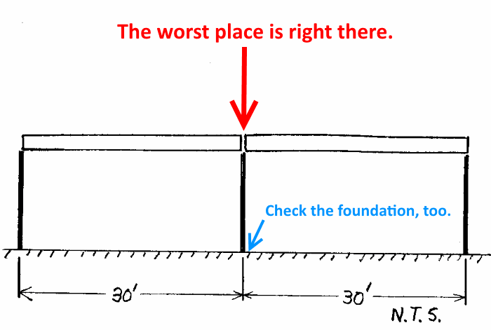
One of the all important variables that we can't nail down is where the 5000# basket is going to fall in the unlikely event that it does fall. It could fall on one of the rigid frames which would be very rigid. Or it could fall in the middle of the thirty foot long beams which would be more flexible. Perhaps the worst case would be if it descended near the edge of the structure such that the basket is only partially supported by the canopy.

BA
 
I will be using RISA 3D to do the structural analysis. This is why I want to use the load with an impact factor (2x, 3x, etc.) I can place the load anywhere on the structure to determine the worst case loading for beams, frames, columns, etc. And can also observe deflection criteria.

In addition to the vertical load, a horizontal component will be added at the point of impact to account for the lateral movement of the basket as it is being moved horizontally with by autocrane. However, horizontal speed is very slow.

There are 2 things I feel that are working to my advantage. 1) The steel basket accounts for half of the total load. It is made of steel pipe framing and sheet metal. If it falls the 12", it will likely deform, thus absorbing some amount of the impact energy, similar to guard rails and car chassis as has been noted previously. 2) The copper pipe inside inside the basket is loosely coiled, so it will have a natural tendency to move about and also absorb energy at impact. By comparison, dropping a 5.0 Kip piece of solid granite would impart much more impact force than this basket with coiled pipe.
 
Yep. Stiffness is the enemy here causing the effective load to increase at a faster rate then the strength. I agree that the most efficient solution will feature some sacrificial element to absorb energy and increase delta t.
 
You can have a look here too :

"Formulas for stress, strain, and structural matrices - Pilkey - 1994" Chapter 10-Dynamic loading - parag 10.5-Impact formulas- table 10.7
 
Hello

If the steel basket is stiff then alot or most of the load will be applied closer to the columns. So you lose the spring effect of the beam.

The fender or sacrifical wood. mentioned above sounds like the way to go.

Energy method is simliar to 1/2 M(Vsquared)=1/2 K (defl squared) OR KE method. You can calc V at impact. And the deflection of structure will give you K (Stiffness).
 
There is no calculation you can devise which could account for the possibility of the load falling seriously off center. The solution is simple; do not allow pedestrian access under the crane while it is operating.

BA
 
Is the variability in the elevation of the basket actually 12", or could the canopy (or parts of it) be raised up so that the potential drop is minimized? Is the horizontal path of the basket defined, or does it vary? If it's defined, then perhaps some type of cradle system that would limit the where the basket could fall would make design of the framework more straightforward.

I see from previous posts that cushioning the basket is not an option, but could you cushion between the canopy and the support structure?
 
I'm with BA ... either a simple real world solution (no pedestrians) or an almost infinite amount of engineering, chasing what-ifs.

another day in paradise, or is paradise one day closer ?
 
Status
Not open for further replies.

Part and Inventory Search

Sponsor

Back
Top