Continue to Site

Eng-Tips is the largest engineering community on the Internet

Intelligent Work Forums for Engineering Professionals

  • Congratulations KootK on being selected by the Eng-Tips community for having the most helpful posts in the forums last week. Way to Go!

beam to support weight of boat 1

Status
Not open for further replies.

ajk1

Structural
Apr 22, 2011
1,791

Given:
Need to store boat over the winter, in boathouse. The boat will be supported on 2 beams, that span 14 feet on centre. Owner tells me that boat weighs 3500 pounds (seems a lot to me) and that I should assume that two-thirds of the weight is on one beam only i.e. 2333 pounds point load at midspan.

Note: Currently the beams are timber, 5.5" wide x 6" deep, based on my on-site measurements. I would assume the load is applied as a point load at mid-span of the beam. When I check the flexural capacity based on #2 spruce, the beams are nowhere near to figuring. Even if I assume #1 Douglas Fir, the Mr is only about half of the required moment of resistance.

Required:
The owner wants to find beams that weigh less so that they are more easily manhandled into place. The beam would of course be laterally unsupported.


How to determine a lighter weight beam than the existing 9 pounds per foot wood beams. i.e. shape, material, etc. The only thing that I can think of would be aluminum tubular section.

Questions:
What do you suggest for beam material and beam shape? If you agree aluminum section, would it be 6061-T6 grade and what size? I can size it in steel, but not experienced in aluminum design.
 
Replies continue below

Recommended for you

You might be able to reduce the weight of a wood beam a little bit by designing a plywood box beam. Top and bottom chords would be regular dimensional lumber and then webs would be plywood. The APA has design guides for plywood box beams. I would not worry about deflection. 3,500 lbs is not unreasonable for a boat and motor, especially if it is a boston whaler or similar. A very basic aluminum hulled boat would weigh less. Very common to see 8x8's and such used, but for smaller spans. 14 ft wide seems quite wide for a typical boathouse slip, much wider than many boats, I would guess it is a double slip. One would have to carefully think through the durability of a plywood box beam, marine plywood, coatings, etc... to prevent deterioration.

I do agree that aluminum would be reasonable. There are quite a few stock W and HSS sections available in 6061-T6.
 
Good point thanks.

wannabeSE said:
Is this beam permanently supported so it is only lifted into place one time (beam support hoist). If yes, how does the expense of aluminum compare to the cost of lifting the two heavier beams 1 time?

It is lifted into place when the boat is put up for storage at the end of each boating season in the fall. He wants the beams to be light enough that he (a senior or nearly senior person) can manhandle the beams into place, even if those beams are more expensive than hiring someone and/or additional equipment to lift them into place. He is a professional person, and quite intelligent, so I think he has considered many possibilities before requesting consideration of a design of lighter beams.

amlinerrichard said:
The boat has to be driven into the boathouse. Put straps in the water under the boat. Bring each end of the strap up and run them through rollers back down to the walkway in the boat house. Crank the straps to raise the boat. You look at the loads on the boathouse walls . You will have to put a few beams from wall to wall to keep the boathouse walls vertical.

The beams sit on the floor and are supported by cribs under each side of the floor opening. The floor opening for the boat is 9'-8". The cribs are set back from the edge of the opening about 2'-2", so the centre to centre span of the beams is about 14'. The boathouse walls have nothing to do with this, although I did not provide enough info in my post to make that clear.

hotrod10 said:
Why would you set any limit on the deflection? I can't see how it would matter, other than a slight increase in stability.

Speaking of stability, you could go with a tall, narrow beam to maximize the bending capacity, and then add a wide end plate (maybe with handholes for easy handling?) or bearing plate to keep the ends from rolling over. That assumes the beam ends rest on a floor, or something else wide enough to support the end plate or bearing plate, of course.

I am looking for guidance from someone on this forum, preferably a boater who has stored their boat over the winter on beams like this, as to whether there should be any limit on deflection, and if so what it should be.

Are you referring to a "steel" beam with end plate? I don't think that would be lighter than the wood beam.

 
As follow-up question:

Does anyone know a website that I could go to that gives the dimensions and plastic section modulus of tubular aluminum beam sections?
 

I was thinking of an aluminum beam. Due to the aforementioned issue of reduced strength for welded aluminum, bolting the end plate (probably with a pair of angles) could be better. Possibly, just bolting a pair of large angles to the sides of the beam would suffice to stabilize the beam and provide handles.

OTOH, at the end of the beam, the stresses are low, so even a large reduction in strength locally at the end might not matter. Be careful, though, - some aluminum alloys are weldable, and some are not.
 
hotrod10 said:
One other consideration I just thought of is there could be a minimum bearing width where the for the keel rests on the support beam. Aluminum or steel may provide a bearing surface that is too hard for the keel of the boat. One of the reasons timber is the go-to material for these types of supports is that it is relatively soft and conforms to the surface of the keel, spreading the pressure evenly over the contact area. If you decide on a metal beam, I would give some thought to the contact area/pressure and consider adding a bearing pad to the top of the beam.

The owner mentioned to me that he uses a saddle, even with the wood beam. But I will emphasize to him that it is even even more important with a steel beam.

3DDave said:
You could probably knock about 1/4 of the weight off those beams by milling out the middle to make it an I-Beam shape without changing the strength in a noticeable way. If you taper the milling, you could probably get to 1/3 the weight; the bending resistance at the supports is the minimum so it doesn't need much web there. You may wish to do this as pockets to leave the ends full section to prevent damage from dropping the beams or dropping things on them

I do not follow. How can you make an "I-Beam" shape out of a wood beam from milling out the centre? It seems to me that would leave a top flange and at bottom flange, but not an "I-beam" shape. Anyway, if you did that, the concentrated load of the boat at midspan above the milled-out section would put a moment onto that part of the top "flange" of the beam, which would make it likely not figure.

PEinc said:
How about making each of the 2 beams out of 4 each, pressure treated, 2x10's. Each single beam could be made out of a pair of 2x10's so that the lifting weight of each half beam is about 16% lighter than your 5.5x6 wood beam [(2x1.5x9.25)/(5.5x6)] = 84% area = 84% weight. Then, after setting each pair of 2x10's, bolt them together to make a 6x10 beam (= 4 each 2x10's standing vertically, side by side, perhaps even with some blocking between the 2x10's to make them wider and more stable). If you really want to reduce lifting weight, make the quadruple 2x10 beam out of 4 each 2x10's, setting them one at a time before bolting them together. PT 2x10's and galvanized all-thread rods are readily available and cheap.
S = 1/6 x 5.5 x 6.0 x 6.0 = 33.0 in.3 for the 5.5 x 6 beam. I = 99.0 in.4.
S = 4(1/6 x 1.5 x 9.25 x 9.25) = 85.5 in.3 for the quadruple 2x10 beam. I = 396 in. 4.

4-2x10's = 4x1.5x9.25=55.5 vs 2-5.5x6 = 66. Very little saving. I am looking to reduce weight by roughly 50% so he can significantly more easily manhandle it into place. Also, how dos he bolt the together after they are put in place, without standing in the water to do so? If thenare bolted together before being slid nto place, he is still left with manhandling the weight of 2-2x10's not 1-2x10.

canuck65 said:
You might be able to reduce the weight of a wood beam a little bit by designing a plywood box beam. Top and bottom chords would be regular dimensional lumber and then webs would be plywood. The APA has design guides for plywood box beams. I would not worry about deflection. 3,500 lbs is not unreasonable for a boat and motor, especially if it is a boston whaler or similar. A very basic aluminum hulled boat would weigh less. Very common to see 8x8's and such used, but for smaller spans. 14 ft wide seems quite wide for a typical boathouse slip, much wider than many boats, I would guess it is a double slip. One would have to carefully think through the durability of a plywood box beam, marine plywood, coatings, etc... to prevent deterioration.

I do agree that aluminum would be reasonable. There are quite a few stock W and HSS sections available in 6061-T6

Plywood beam sounds worth looking into. But if I do not have to worry about deflection, then a 5x3x 1/4" tubular aluminum section at about 4.25± plf (46%± of weight of existing 5.5"x6" wood beam) and with deflection = 2.05"± would seem to work. 60 pds per beam vs. 130 pds per beam. Perhaps that solves the problem. But are you sure that 2" deflection on 14 foot span is ok, and will have no detrimental effect?
 
ajk1 said:
Does anyone know a website that I could go to that gives the dimensions and plastic section modulus of tubular aluminum beam sections?
Your best bet would be the aluminum design manual,
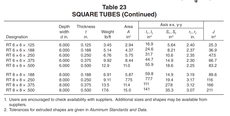
In the past I have run into problems where the contractor could not find the sections specified (pulled from tables). So, make sure you check availability before specifying a particular section. Here are some sections from the 2010 Aluminum Design Manual:
Aluminum_Tubes_v1sz0y.png

Aluminum_Tubes_-_R_dmtvha.png
 
ajki, you are smart enough to design the beam; you certainly are smart enough to figure a way to bolt a few 2x10's together. Consider bolting the 2x10's together near the two ends, where the owner can stand on the slab. Consider standing in a row boat. Consider hanging a pulley from the ceiling to lift and set a heavier beam.

Again, 2x10's are relatively light, strong, cheap, and readily available. As always, a sketch would help us to better understand the problem. Can the final, heavy beams be sitting on the floor out in front of the boat's bow and then be slid or rolled out under the boat after the boat is hoisted? I would not want to support my boat with beams that allow 2 inches of deflection for a 14' span.

 
"I would not want to support my boat with beams that allow 2 inches of deflection for a 14' span."

Why not? I could understand that from an average person, as it could look as if it would fail, but as an engineer, you know that isn't case.
 
Sorry if this was discussed, if so I missed it: If you are going to use a deep, narrow section you must prevent it from rolling over.

Regards,

Mike

The problem with sloppy work is that the supply FAR EXCEEDS the demand
 
I'm sorry to repeat myself, but I don't like the idea of balancing the boat on the point of it's hull, which seems to me what you're doing to create a point load mid-span.

I'd support the boat on pads, on the inclined hull faces.

I'm assuming this is a power boat with a planning hull.

another day in paradise, or is paradise one day closer ?
 
Allowing 2" of deflection supporting a boat in a typical boathouse would not bother me at all, as long as the strength is there.

There should be wedges or chocks that conform to the hull shape incorporated into the design, otherwise the boat will have to remain supported by the lifting slings for the entire winter. If there are no wedges or chocks, the boat will tip over unless it is flat bottomed, which is unlikely.

I might be inclined to put two of the aluminum sections you have sized under the heavy end and keep one under the lighter end. Some increased cost, but will slightly reduce the deflection and provide a little redundancy and a little extra capacity.
 
As mentioned by others "Consider hanging a pulley from the ceiling to lift and set a heavier beam."
Also as mentioned by others the lack of information drawings and pictures has already as expected some entertaining side trips. The vertical height available above the operating installed height of the existing wooden beams would seem to be just one of many useful bits of information not yet submitted as evidence.


The original Post mentions the " existing 9 pounds per foot wood beams" and a 14 foot span.
I'm thinking It would not take much of a hoist or roof system to lift a 200 pound beam.


A hoist to lift the boat was mentioned. With it attached to each of the beams in question lying on the boat house floor, a hook run to the roof ridge beam etc would allow the same hoist to lift the existing beams with 10X surplus capacity.
 
Tmoose,

The way these systems typically work is that the main hoist is used, with slings, to lift the boat up off of the beams. The boat remains above the beams, hung from the hoist, and the main hoist is unavailable for moving/lifting the beams. Then the beams need to be moved out of the way, typically by hand, and moved somewhere for summer storage, then the boat is lowered into the water once the beams have been moved. There are many variations, however, this is most common. There is not much room to maneuver the beams when the boat is hung from the lift.
 
canuck65 said:
Allowing 2" of deflection supporting a boat in a typical boathouse would not bother me at all, as long as the strength is there.

There should be wedges or chocks that conform to the hull shape incorporated into the design, otherwise the boat will have to remain supported by the lifting slings for the entire winter. If there are no wedges or chocks, the boat will tip over unless it is flat bottomed, which is unlikely.

I might be inclined to put two of the aluminum sections you have sized under the heavy end and keep one under the lighter end. Some increased cost, but will slightly reduce the deflection and provide a little redundancy and a little extra capacity.

Thank you Canuck65. You seem to have understood the question precisely, you seem to be familiar with similar situations, and you have provided me with clear understandable advice, free of extraneous gratuitous but unhelpful remarks. Perfect!! Why can't everyone on this system be like you? I very much appreciate what you have said, and will proceed along these lines, as they seem to be wisely based and make a lot of sense to me as a structural engineer. I will check with the owner if he can send me photos of whatever wedges or chocks that he currently uses.

 
dauwerda said:
Your best bet would be the aluminum design manual,
In the past I have run into problems where the contractor could not find the sections specified (pulled from tables). So, make sure you check availability before specifying a particular section. Here are some sections from the 2010 Aluminum Design Manual:

Thanks for the reference to the Aluminum Manual. Is kind of a pricey manual tohave to buy to design one beam.
 
I don't believe it was the intention of anyone posting here to respond with "extraneous gratuitous but unhelpful remarks", but if you feel some of us were wasting your time by responding, I for one can certainly refrain from responding to your posts in the future.
 
ajk1 said:
Thanks for the reference to the Aluminum Manual. Is kind of a pricey manual tohave to buy to design one beam.
I agree, that is why I included the screen shots to of the tubular section properties that you were asking for.
 
For what it's worth, I thought amlinerrichard's suggestion for an overhead lifting system was the best of the bunch for the situation you described. A pair of overhead gantries, whether freestanding or supported by the walls, with straps wrapping under the boat and attached to motorized hoists, would allow the boat to be lifted into its stored position without the owner having to ever move a beam. It could all be accomplished with the push of a button (well, technically 4 buttons).
 
Thanks all for the time you have spent on this much appreciated.
 
A bit out of left field, but FRP is reasonably light, and since this is somewhat low loads you might be able to reasonably use an 8 or 10 inch deep FRP section. Connections are irritating though and would take some thinking.

If you aren't worried about deflection, it looks like you might be able to get to somewhere in the 6.5lb/ft range.
 
Status
Not open for further replies.

Part and Inventory Search

Sponsor