Continue to Site

Eng-Tips is the largest engineering community on the Internet

Intelligent Work Forums for Engineering Professionals

  • Congratulations waross on being selected by the Eng-Tips community for having the most helpful posts in the forums last week. Way to Go!

Bearing arrangement - comments please

Status
Not open for further replies.

GRAY190

Mechanical
Jun 11, 2016
6
I'm designing a small wind turbine drivetrain that is handling significant axial load in 1 direction (Fa >> Fr) and a very small radial load on both bearings.

1. Locating / non locating bearing arrangement. Is it possible to use a spherical roller bearing for the locating bearing and a radial insert ball bearing for the other, like this??
Or are we limited to the examples like in the guides from FAG & SKF?
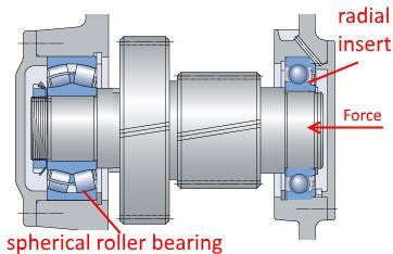
proposed_locating_non_locating_arranagement_ktahwn.jpg


2. Tapred bore with adapter sleeve, lock nut and locating ring + stepped shaft - can they accommodate significant axial loads? I've rlooked at the SKF, FAG and Timken design guides, but they don't mention anything on this.

2. Locating bearing housings: Is it possible to use plummer block units instead of flanged housings to house the locating bearing? If I use plummer block housings, the thrust forces will create moment on the 2 bolts fastening the plummer block housing down (4 bolt ones not available for the size I'm using). Welding the block down would risk misalignment.

I've tried googling (can't find) and tried calling Timken, Schaeffler, Koyo and SKF in my country to get help from their application engineers, but I keep on getting redirected to sales all the time.

Thank you!
 
Replies continue below

Recommended for you

Is there a reason you're avoiding a thrust bearing? As you say the axial force is much greater than the radial force, can you not add in a thrust bearing to take care of this and then use a smaller radial bearing in place of the spherical roller bearing?

What are the sizes that you're looking at? You mention that as a limiting factor but don't tell us what it is...

Aidan McAllister
Metallurgical Engineer
 
@AidanMc - Size, cost and lead times are the main issues.

I considered using thrust bearings, but due to small shaft size (25mm metric dia) thrust bearings e.g. thrust spherical roller, thrust taper roller etc are not manufactured in this size; or require a 3-4 months of lead time for product to reach my country.

I chose spherical roller bearings because it can tolerate misalignment and has the highest Cr and Cor (intermittent rotation) compared to thrust ball bearings and double row angular contact bearings.
 
Is the image in the OP representative of your arrangement? A couple of helical gears with no turbine etc hung outboard?

What is the value of the "significant" axial load ?
And operating rpm?
 
@Tmoose - The image isn't representative. I don't have CAD drawings yet because I haven't firmed up the bearing choice. Hence the picture was taken from the SKF website and then changed a bit.

The significant axial load is about 14kN. Operating rpm fluctuates since its a wind turbine, but max operating rpm should be 500rpm.

 
Also, I managed to get in touch with an application engineer from one of the manufacturer. He says that it is recommended to use matched pair tapered roller bearings ("X" configuration) as the fixed bearing, but they don't normally selling housings that can accommodate taper roller bearings or matched pairs.

Do you custom fabricate these housings?

Or do you know where to find them off the shelf? As much as possible, I'd like to avoid custom fabrication, due to the cost and time involved.

Thanks!
 
GRAY190,

Your arrangement looks to me to be optimal for radial force, with some capability to manage axial force.

Look up spindle bearings. There is a series of angular contact bearings out there that are manufactured very accurately such that they pre-load when they are assembled face to face. That alone may be enough to hold your turbine. Aside from cost, there is no harm in keeping your deep groove bearing.

--
JHG
 
1. I see both locating bearings there

25mm is not very small. There are many thrust bearing options, like: 30205 , 31305, 51105, 51305
Just curious, where are you located?

Can you provide shaft length?
 
By the way, good news. I managed to ring up the application engineers from one of the bearing companies. Got some help from them.

@drawoh "optimised for radial force" - That's a big problem. This being a model wind turbine the axial force is way higher than the radial force. I may not even have enough radial force for preloading the non-locating bearing.

@lukin1977 - I'm in Singapore. I have multiple authorised distributors in my city, so I have the quoted prices of these bearings. The total shaft length is about 100-150mm (design not frozen yet).

The problem is finding suitable housings for locating double row tapered roller bearings. The distributors all have housings for spherical roller bearings and radial insert bearings, but none for taper roller bearings or cylindrical roller bearings. They asked me to custom fabricate, which I'd only do if I had no choice.

@BrianE22 - Yes, pretty much all reputable vendors offer calculation data for calculating the equivalent axial to radial load. In fact, I built my own equivalent load calculator so calculations are no problem for me. Getting suitable housings is the problem now.


Is it possible to use a spherical roller bearing for the locating bearing and a radial insert ball bearing for the other, like this??
Or are we limited to the examples like in the guides from FAG & SKF?

Your example looks a little odd for a thrust-heavy application.

Why would you _not_ exploit the bearing manufacturers' accumulated experience in the form of guides?

How did you manage to get yourself locked into a 25mm straight shaft at this early stage?

Have you looked at the preassembled factory-set cartridge bearing assemblies now common on automobile front wheels?

Your example appears to show a pair of gears between the bearings, yet you state minimal radial loads. Are gears, and associated separating forces, present, or not?


Mike Halloran
Pembroke Pines, FL, USA
 
Get the housings custom made then
At that size it should not be very difficult nor time demanding to fabricate
 
Update: I managed to contact one of the application engineers from FAG. I'm working through the issues with them.

The diagram is misleading - it's a direct drive system, no gears and whatnot.

I almost managed to find 35mm Timken tapered roller bearing housed units, but too bad, they don't stock them in Singapore. Gave up, am now custom making my own housings.
 
I realize this is a bit old, but I have experience with this bearing layout. Beware the spherical roller bearing in mostly axial load. While the L10 life is attractive, the reality is that one set of rollers just floats along in air and the rollers will often stop rotating. If the load is extremely constant and free of shocks/impulses, the non-rotating rollers are harmless. But in the event there is a sudden external load that brings the inboard rollers into rotation, those rollers will skid and fail suddenly. Another factor is that spherical rollers in axial load are unstable - the axial force wants to flip each roller around - such that when the bearing approaches failure it wears on the cage and the bearing will lock up or burst when the wear reaches the point the rollers have enough free play to spin around. It is not a forgiving failure mode to recover from. Last but not least, check the axial float of the assembled spherical roller bearing. For 23xxx series the geometry is not bad but for 21xxx and 22xxx series the small radial clearance still creates significant end float.

In my case, we switched from the spherical roller to a deep groove ball bearing with C3/C4 clearance (an angular contact ball will work too) since there is only one set of rolling elements and they all get a share of the load. The extra clearance shifts the load path angle to make the contact more "angular". While deep groove ball bearings are usually seen as "radial" bearings, they can perform very well with mostly axial load under appropriate circumstances.
 
MikeHalloran said:
Why would you _not_ exploit the bearing manufacturers' accumulated experience in the form of guides?

While I roundly trust bearing manufacturers, they each have their biases. SKF for example invented the spherical roller bearing, so they will tend to push spherical roller bearings. Timken invented the taper roller bearing, so of course they push those.
 
Status
Not open for further replies.

Part and Inventory Search

Sponsor