archibaldtuttle
Materials
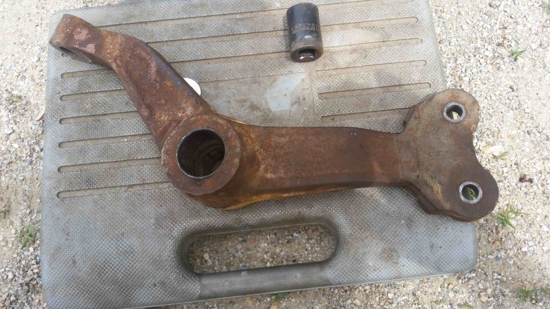
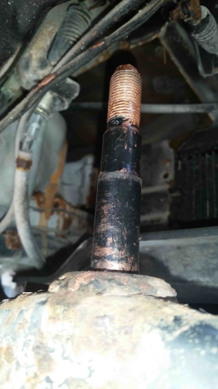
hopefully if all goes well there are a picture of a steering link and mounting post below. this is from small gray market japanese truck from 1991. newer models use bearings, oldermodels used bushing constructed of two steel collars bonded by rubber similar to a shock mount bushing.
parts and parts diagrams far and few between so i'm just trying to fill the space between the bore and post most sensible way i can. could be either roller/needle bearing or sleever bearing/bushing. very low use, just trying to get it below a half turn of play in the steering wheel.
for easy field application i'm trying to figure how close i can spec the ID and OD to the actual sizes of the bore and post. the bore currently is a little worn and i'd probably take it out to either 30 mm or 1.25 (currently avg. 1.160 so maybe it was 29 or 1 and 1/8 to start ??? and the post causes me a little more headache because it is turned down. the bottom third is just over 3/4 at .77 and the top is about .71.
my current set up is the old steel center collar with a 1" copper pipe pounded over it which gives me about 30 to 40 thousandths lash inside and outside. just trying to firm that up a little.
i'm not having great luck specing bearings because of the odd sizing. can i treat the .77 as if it were 20mm or is there an oversize 3/4. what would be standard clearance for field install. 10 thousandths difference in diameter or closer?
might be able to play with a few more copper sizes and slip fittings to limit the lash on the inside toward the post to 15 thousandths. and i could pretty readily have the bore taken up to 1.25 and that would leave no lash outside on a 1" copper slip coupling.
but i'm think it would be preferable to actually have a grease fitting and intend for the bushing to stay stationary, make it a little long and it with the nut like shoulder and then put a zerk fitting into the outside of the bore and overbore a bit to leave grease space. how much space should i leave for grease to keep play down but let grease in and insure that the rotation takes place along this surface . . .
this thing gets low use at low speeds on farm so i'm not worried about getting it to OEM specs, which apparently don't last long anyway as folks who handle used parts say these steering links are going all the time. and with this design i can always replace worn parts with copper pipe readily available that way. what would be advisable grease space. is there something wrong with copper as a sacrifical bushing in this application with virtually no rpms but levered side load. they always seem to use oil impregnated bronze but i'm got to go with what i got. i can't find any bronze that is going to do much for me and the copper built up from two pieces of pipe and two couples is pretty close.
sorry for the novel, was trying to include specifics and my design ideas.
brian


